Rockwell Automation Publication 750-IN001O-EN-P - October 2014 63
Lift and Mount the Drive Chapter 3
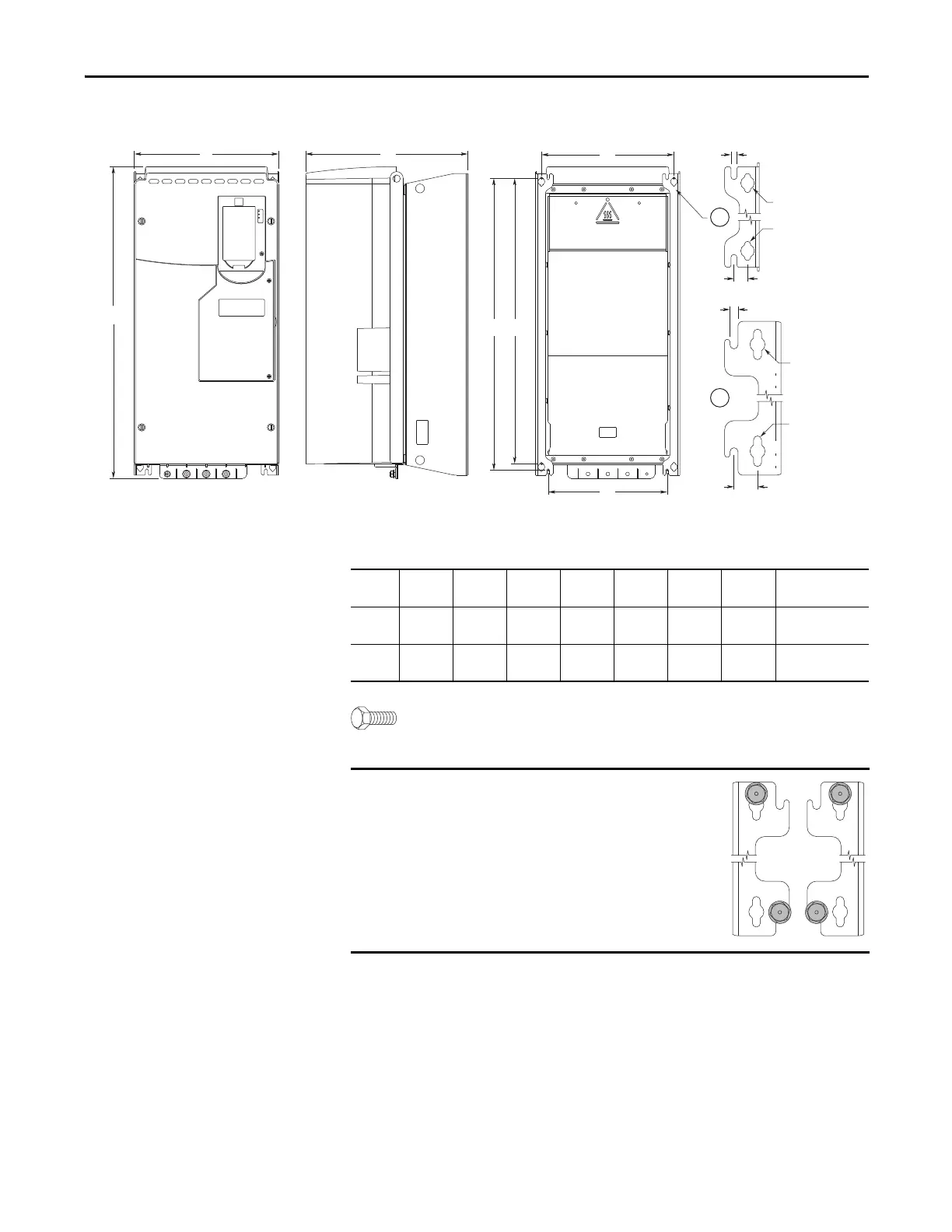
Figure 25 - IP00, NEMA/UL Open Type, Wall Mount Frames 6 and 7 (Frame 6 Shown)
Dimensions are in millimeters and (inches).
Frame 6: M6 (#12) mounting hardware recommended.
Frame 7: M8 (5/16 in.) mounting hardware recommended.
GE
F
D
C
6.4 (0.25)
14.5 (0.57)
A
B
ø6.5 (0.26)
ø14.5 (0.57)
6
7
8.5 (0.33)
25.0 (0.98)
ø8.5 (0.33)
ø16.0 (0.63)
Frame A B C D E F G Weight
kg (lb)
6 308.0
(12.13)
665.5
(26.20)
346.4
(13.64)
283.0
(11.14)
623.0
(24.53)
254.0
(10.00)
609.0
(23.98)
38.6
(85.0)
7 430.0
(16.93)
881.5
(34.70)
349.6
(13.76)
380.0
(14.96)
838.0
(32.99)
330.0
(12.99)
825.0
(32.48)
72.6…108.9
(160.0…240.0)
Always install mounting hardware in all four
corners of the mounting legs for stability.
Only install mounting hardware through the top
key holes to help insure the drive is securely
fastened to the mounting surface.
At the bottom of the mounting legs, either the
key holes or optional open mounting slots may
be used.

 Loading...


