Do you have a question about the Allen + Roth A102002101 and is the answer not in the manual?
Important warnings and guidelines for product installation and use.
Steps and requirements before starting product assembly.
Assemble posts (A1/A2) with base cover (N2) and base (M2) using bolts (AA) and washers (BB).
Assemble posts (A3/A4) with base cover (N1) and base (M1) using bolts (AA) and washers (BB).
Connect side beams (D1/D2/D3/D4) with beam connector (D5) using specified bolts and washers.
Insert posts (A5/A6) into posts (A1/A2) using bolts (NN) and washers (BB).
Attach side beams (D1/D2) to posts (A1/A2) using bolts (HH) and allen key (Z1).
Attach side beams (D3/D4) to posts (A3/A4) using bolts (DD), washers (BB), and spring washers (EE).
Attach side beams (D3/D4) to posts (A3/A4) using bolts (HH) and allen key (Z1).
Connect front beams (B3/B4) with beam connector (D5) using specified bolts, washers, and spring washers.
Connect rear beams (C1/C2) with beam connector (D5) using specified bolts, washers, and spring washers.
Attach rear beams (C1/C2) to posts (A5/A6) using bolts (CC), washers (BB), and spring washers (EE).
Attach beams (B3/B4) to posts (A3/A4) using bolts (DD), washers (BB), and spring washers (EE).
Attach beams (B3/B4) to posts (A3/A4) using bolts (HH) and allen key (Z1).
Insert hooks (LL) into beams (B5/D6) and attach plastic caps (MM) to side beams.
Attach beams (B5/D6) to other beams (D1/D2/D3/D4/B3/B4) using bolts (DD) and washers (BB).
Attach support bar (K) to side beam (D3/D4) and front beam (B3/B4) using specified bolts, washers, and spring washers.
Attach cover (J) using bolts (DD) and washers (BB).
Connect support beams (F1/F2/F3) with beam connector (F8) using bolts (NN) and washers (BB).
Connect support beams (F1/F2/F3) with beam connector (F7) using bolts (CC), washers (BB), spring washers (EE), nuts (JJ), and caps (OO).
Attach support beams (F1/F2/F3) to side beams (D1/D2/D3/D4) using bolts (DD) and washers (BB).
Connect top beams (E1) to top beams (E2) with beam connector (E8) using bolts (NN) and washers (BB).
Attach top beam (E2) to rear beams (C1/C2) using bolts (DD) and washers (BB).
Attach top beam (E1/E2) to support beams (F3) using bolts (II), washers (BB), spring washers (EE), nuts (JJ), and caps (OO).
Attach top beam (E1) to support beams (F1/F2) using bolts (PP), washers (BB), spring washers (EE), nuts (JJ), and caps (OO).
Attach top beam (E1) to support beams (F1/F2) using bolts (DD) and washers (BB).
Attach top beam (E1) to front beam (B3/B4) using bolts (DD) and washers (BB).
Connect top side beams (E4/E6) to rear beam top side beams (E3/E5) with connector (E7) using bolts (NN) and washers (BB).
Attach top side beams (E4/E6) to posts (A5/A6) using bolts (FF) and washers (BB).
Attach top side beams (E3/E5) to posts (A3/A4) using bolts (FF) and washers (BB).
Insert PC panels (R4/R6) and (R5/R7) into side beams and top side beams.
Insert PC panel (R3) into the lower slot of the top beam (E2).
Lock PC panel (R2) to PC panel (R3) and fully insert PC panel (R3) into top beam (E2).
Insert PC panel (R2) into the middle slot of the top beam (E2).
Lock PC panel (R1) to PC panel (R2) and fully insert PC panel (R2) into top beam (E2).
Insert PC panel (R1) into the upper slot of the top beam (E2).
Attach decorative railings (I3/I4) to top side beams (E4/E6) using bolts (AA) and washers (BB).
Attach decorative railings (I3/I4) to top beam (E2) using bolts (AA) and washers (BB).
Attach L-shaped brackets (Q1) to top side beams (E6/E4) and side beams (D1/D2) using bolts (AA) and washers (BB).
Attach decorative railings (I1/I2) to top beams (E3/E5) using bolts (AA) and washers (BB).
Attach decorative railings (I1/I2) to top beam (E1) using bolts (AA) and washers (BB).
Attach wall mount sheets (L) to posts (A1/A2) using bolts (DD) and washers (BB).
Secure the gazebo to the wall with wall mount sheets (L) using expansion bolts (GG).
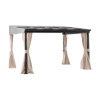
Hang the curtain (P) to the netting tube of front and side beams.
Hang the netting (O) to the netting tube of front and side beams.
Secure the netting (O) to the posts (A1/A2/A3/A4) using loop and hook.
Secure the gazebo to the ground using stakes (KK).
Secure the gazebo to the ground using stakes (KK).
Explains different ways to move the top PC panels (R1, R2, R3).
Details the warranty coverage, exclusions, and customer service contact.
| Product Name | Allen + Roth A102002101 |
|---|---|
| Category | Outdoor Furnishing |
| Frame Material | Steel |
| Cushion Color Family | Beige |
| Color | Beige |
| Assembly Required | Yes |
| Material | Fabric |