EasyManua.ls Logo

Allied Telesis AT 9924SP AT-9924SP-30 AT-9924SP-30 - User Manual

Allied Telesis AT 9924SP  AT-9924SP-30 AT-9924SP-30
56 pages
Print Icon
To Next Page IconTo Next Page
Loading...
C613-16092-00 REV D
www.alliedtelesis.com
AlliedWare
TM
OS
How To |
Introduction
Putting a ring of Ethernet switches at the core of a network is a simple way to increase the
network’s resilience—such a network is no longer susceptible to a single point of failure.
However, the ring must be protected from Layer 2 loops. Traditionally, STP-based
technologies are used to protect rings, but they are relatively slow to recover from link
failure. This can create problems for applications that have strict loss requirements, such as
voice and video traffic, where the speed of recovery is highly significant.
This How To Note describes a fast alternative to STP: Ethernet Protection Switching Ring
(EPSR). EPSR enables rings to recover rapidly from link or node failures—within as little as
50ms, depending on port type and configuration. This is much faster than STP at 30 seconds
or even RSTP at
1
to 3 seconds.
What information will you find in this document?
This How To Note begins by describing EPSR in the following sections:
"How EPSR Works" on page 3
"Establishing a Ring" on page 4
"Detecting a Fault" on page 5
"Recovering from a Fault" on page 5
"Restoring Normal Operation" on page 7
Next it gives step-by-step configuration details and examples in the following sections:
"How To Configure EPSR" on page 8
"Example
1
: A Basic Ring" on page 11
"Example 2: A Double Ring" on page 14
Configure EPSR (Ethernet Protection Switching
Ring) to Protect a Ring from Loops
Question and Answer IconNeed help?

Do you have a question about the Allied Telesis AT 9924SP AT-9924SP-30 AT-9924SP-30 and is the answer not in the manual?
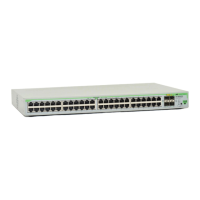
Allied Telesis AT 9924SP AT-9924SP-30 AT-9924SP-30 Specifications

General IconGeneral
Device TypeSwitch
Power over Ethernet (PoE)No
ManageableYes
Uplink Ports4
FeaturesQoS
Dimensions440 x 210 x 44 mm
Storage Temperature-25 - 70 °C

Summary

Introduction to EPSR

Products and Software Versions Supported

How EPSR Works

EPSR Components Explained

Defines key terms and elements within an EPSR domain, such as Master Node, Transit Node, and VLANs.

Establishing an EPSR Ring

Details the process by which an EPSR ring is initially formed and operational.

Detecting EPSR Ring Faults

Describes the methods EPSR employs to identify link or node failures within the ring.

Recovering from EPSR Faults

Outlines the steps EPSR takes to restore traffic flow after a detected fault.

Restoring Normal EPSR Operation

Explains how EPSR transitions back to its normal state after a fault is resolved.

How To Configure EPSR

Modifying the Control VLAN for EPSR

Details the procedure and considerations for changing the control VLAN settings for EPSR.

Example 1: A Basic EPSR Ring

Example 2: EPSR with a Double Ring

Example 3: EPSR and RSTP Integration

Example 4: EPSR with Nested VLANs

Example 5: EPSR with Management Stacking

Example 6: EPSR with an iMAP

Checking Master Node Configuration

Details how to verify the operational status and settings of the EPSR master node.

Configure iMAP as Transit Node

Provides specific commands for configuring an iMAP as a transit node in EPSR.

Classifiers and Hardware Filters in EPSR

Ports and Recovery Times

IGMP Snooping and Recovery Times

Health Message Priority Configuration

Describes the importance and configuration of priority for EPSR Health messages.

EPSR State and Settings

SNMP Traps for EPSR Monitoring

EPSR Counters

Debugging EPSR Operations

Master Node (Node A) Debug Output

Shows sample debug logs for the master node during EPSR operation and fault scenarios.

Transit Node (Node B) Debug Output

Presents sample debug logs for a transit node in EPSR during fault and recovery events.

Link Down Between Two Transit Nodes Debug

Illustrates debug output when a link between two transit nodes fails and recovers.

Related product manuals