Do you have a question about the Allied Telesis AT-9924SP and is the answer not in the manual?
Describes the ASIC switch chip and its non-blocking Layer 2/3 IP switching capabilities.
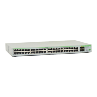
Key features, port configurations, and expansion card support for AT-8948 and x900-48FE models.
Describes the ASIC switch chip and high-performance IPv4 switching.
Key features of the AT-9924T, including gigabit ports and PSUs.
Details the processor, memory, and storage options for expandable models.
Key features of the SwitchBlade x908, including expansion bays and stacking.
Explains Link/Activity and Duplex/Collision LEDs for Fast Ethernet ports.
Describes Power, Fault, and CompactFlash/SD card status LEDs.
Explains LEDs for stack master, member, and link status on SwitchBlade x908.
Details the console port for initial configuration and management.
Describes the dedicated Ethernet port for management traffic.
Information on SFP transceivers, speeds, and duplex modes.
Approved XFP modules and compatibility for expansion slots.
Details stacking connections on SwitchBlade x908 and expansion modules.
Lists expansion modules like XFP and SFP for AT-9924Ts.
Lists XEM expansion modules for various x900 and SwitchBlade models.
Details CompactFlash card usage, installation, and testing.
Information on SD card usage, insertion, and data display.
Describes supported SDRAM DIMMs and installation verification.
Wiring diagrams for connecting terminals and modems via RS-232.
Requirements for twisted pair cables and pin assignments for LAN connections.
Details cable testing and reporting of cable lengths.
Table showing appropriate PSUs and fans for each switch model.
Key features, specifications, and LEDs for PWR01 PSU.
Key features, specifications, and LEDs for PWR05 PSU.
Explains how the AT-ACC01 card accelerates IPv6 routing.
Steps to confirm the accelerator card is installed and recognized.
Instructions for installation and setting server preferences.
Commands to download files from the TFTP server.
Steps to set up HyperTerminal for switch connection.
Details on COM port, baud rate, data bits, parity, stop bits, and flow control.
Startup sequence for switches running AlliedWare Plus.
Details startup sequence and messages for older switch models.
How to perform LAN port tests using a crossover cable.
Steps to enter diagnostics mode via terminal connection.
Overview of diagnostic sub-menus and control keys.
Initial checks for common problems like no link or power.
Identifies causes and solutions when the Fault LED is on.
Lists all available documentation for the x900 Series and SwitchBlade.
Information on How-To Notes, MIBs, and Visio stencils.
| Model | AT-9924SP |
|---|---|
| Ports | 24 |
| Uplink Ports | 4 |
| Power over Ethernet | No |
| Switching Capacity | 48 Gbps |
| Forwarding Rate | 35.7 Mpps |
| Weight | 3.5 kg |
| Power Supply | AC 100-240V |
| MAC Address Table | 16K |
| Jumbo Frame Support | Yes |
| Operating Temperature | 0°C to 50°C |
| Type | Managed |
| Dimensions (W x D x H) | 440 x 270 x 44 mm |
| Storage Temperature | -40°C to 70°C |
| Humidity | 10% to 90% (non-condensing) |