AT-MC601 and AT-MC602 Installation and User’s Guide
19
The AT-MC601 and AT-MC602 network extenders feature automatic
MDI/MDI-X. Each port automatically determines the configuration of the
port on the device to which it is connected and then configures itself
appropriately. For example, if a port on a network extender is connected
to a port on a bridge, which is typically wired as MDI, the port on the
network extender automatically configures itself as MDI-X. This feature
allows you to use either straight-through or crossover cables when
connecting devices to the network extender.
Auto-negotiation
The network extenders auto-negotiate the speed and duplex mode of
the Ethernet link, so that the link comes up in the highest performance
configuration supported by both ends.
Half- and Full-duplex Mode
Duplex mode refers to the way an end-node sends and receives data on
the network. An end-node can operate in either half- or full-duplex
mode, depending on its capabilities. An end-node that is operating in
half-duplex mode can either send data or receive data, but it cannot do
both at the same time. An end-node that is operating in full-duplex
mode can send and receive data simultaneously. The best network
performance is achieved when an end-node can operate at full-duplex,
since the end-node is able to send and receive data simultaneously.
The AT-MC601 and AT-MC602 network extenders can operate in either
half- or full-duplex mode. The network extender can operate with end-
nodes capable of either half-duplex, full-duplex, or that can auto-
negotiate the duplex mode. However, it is important to remember that
the two end-nodes connected to the ports on the network extenders
must be able to operate in the same duplex mode.
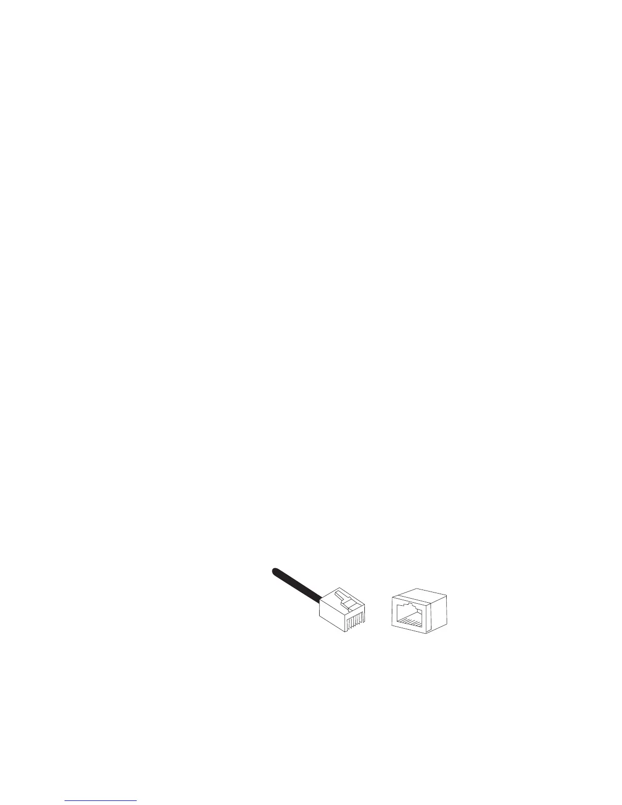
RJ-45 Port Pinouts
Figure 4 illustrates the pin assignments of an RJ-45 connector and port.
Figure 4 RJ-45 Connector and Port Pin Assignments
8
8
1
1
 Loading...