Do you have a question about the Allied 4SCU13LE/B and is the answer not in the manual?
Explains the alphanumeric code used to identify specific model configurations and features.
Provides key physical dimensions, voltage, current, compressor, and fan motor specifications.
Lists the physical size (width, depth, height) and shipping weight for each model.
Lists optional system accessories, their application, and corresponding kit numbers for enhanced functionality.
Presents cooling capacity (BTUH), EER, and SEER ratings for various indoor/outdoor unit matches.
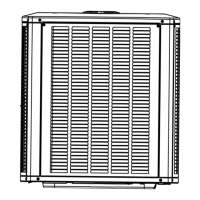
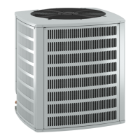
General guidance and critical considerations for installing the outdoor unit correctly and safely.
Requirements for the foundation to ensure stability and proper operation, preventing vibration.
Instructions for raising the unit base to prevent ice or water damage and ensure drainage.
Minimum spacing required around the unit for airflow, service access, and heat dissipation.
Specific considerations for mounting units on rooftops, including structural support and wind protection.
Explains the operation and maintenance of service valves, including Schrader port access and stem operation.
Details the function and distinct construction of ball-type service valves for suction lines.
Examples of using hangers and ties to properly isolate and support refrigerant lines.
Shows correct methods for transitioning refrigerant lines between vertical and horizontal runs.
Illustrates proper installation of vertical refrigerant lines, including insulation and support.
Demonstrates correct installation of horizontal refrigerant lines, emphasizing support and insulation.
Critical instructions for routing refrigerant lines, focusing on vibration dampening and avoiding contact with structures.
Procedures required for converting a system from R-22 to R-410A, including component replacement.
Guidelines for flushing line sets and indoor coils when converting or if contamination is present.
Specific steps for attaching the check expansion valve to the indoor coil's liquid line housing.
Guidance on correct placement and installation of the sensing bulb for accurate temperature readings.
Instructions for connecting the equalizer line to the vapor line port for proper valve operation.
Detailed steps for connecting gauges, pressurizing with nitrogen, and verifying system integrity.
Describes the unit's operation sequence during cooling mode, initiated by thermostat demand.
Details the sequence of events when the cooling demand is satisfied and the system shuts down.
Essential checks and procedures to perform before initial unit operation to ensure safety and performance.
Methods and considerations for charging the system with refrigerant, including weigh-in and adjustment techniques.
Key inspection points for regular service visits by a qualified technician.
Instructions for cleaning or replacing air filters to ensure proper airflow and prevent system issues.
Guidance on cleaning the indoor coil, recommending professional service if needed.
Procedure for checking and clearing the condensate drain line to prevent water backup.
Advice on cleaning outdoor condenser coils to maintain efficiency and prevent damage.
Recommendations for preserving the unit's finish, including waxing and avoiding direct water spray.
Outlines procedures for connecting gauge sets, checking system parameters, and adjusting refrigerant levels.
Methodology for measuring and adjusting indoor coil airflow using the Delta-T process for optimal performance.
Detailed procedures for accurately charging the 13 SEER system using various methods.
| Model | 4SCU13LE/B |
|---|---|
| SEER Rating | Up to 13 |
| HSPF Rating | Up to 7.7 |
| Refrigerant | R-410A |
| Compressor Type | Scroll |
| Voltage | 208/230 |
| Phase | 1 |
| Type | Heat Pump |
| Indoor Unit Dimensions (H x W x D) | Varies by model |
| Indoor Unit Weight | Varies by model |