Do you have a question about the Allied 4HP14B and is the answer not in the manual?
Explains the alphanumeric code for model identification.
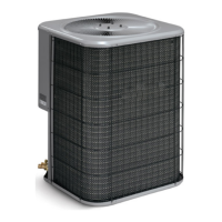
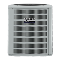
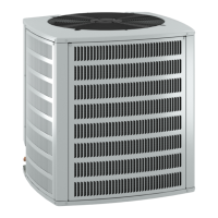
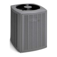
Provides key electrical and physical characteristics of the units.
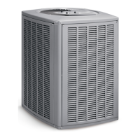
Lists the physical dimensions and shipping weight of the units.
Explains the alphanumeric code for model identification.
Provides key electrical and physical characteristics of the units.
Lists the physical dimensions and shipping weight of the units.
Explains the alphanumeric code for model identification.
Provides key electrical and physical characteristics of the units.
Lists the physical dimensions and shipping weight of the units.
Provides key electrical and physical characteristics of the units.
Lists the physical dimensions and shipping weight of the units.
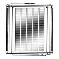
Illustrates and labels key components of the outdoor unit.
Details usage of manifold gauge sets and service valves for system checks.
Lists recommended torque values for various fasteners in HVAC components.
Provides guidelines for using manifold gauge sets with HFC-410A systems.
Discusses considerations for positioning the outdoor unit for optimal performance.
Specifies requirements for a stable and level foundation for the outdoor unit.
Advises on elevating the unit for drainage and snow clearance.
Details minimum clearance requirements for proper unit airflow and service access.
States the acceptable outdoor temperature ranges for cooling and heating modes.
Provides guidelines for installing units on rooftops, including elevation.
Emphasizes the importance and installation of the filter drier for system reliability.
Outlines best practices for installing refrigerant line sets to ensure proper operation.
Illustrates how to transition refrigerant lines from vertical to horizontal runs.
Shows proper installation of vertical refrigerant line runs.
Demonstrates correct methods for installing horizontal refrigerant line runs.
Details the steps for installing the indoor expansion valve unit.
Provides instructions for correctly mounting the sensing bulb.
Outlines the procedure for installing the equalizer line connection.
Instructions for preparing refrigerant line ends before brazing.
Steps to remove service port caps and cores before brazing.
Guide on connecting gauges for brazing with nitrogen flow.
Protects valve seals during brazing with water-saturated cloths.
Details the process of flowing nitrogen during brazing.
Instructions for brazing the line set to service valves.
Final steps after brazing, including cooling and removing cloths.
Procedure for checking the system for refrigerant leaks using pressure and detector.
Steps to evacuate the system to remove air and moisture using a vacuum pump.
Explains thermostat terminal designations for non-communicating systems.
Describes the emergency heat function available in some thermostats.
Details pressure switches, their connections, settings, and lockout features.
Describes the lockout feature triggered by multiple pressure switch trips.
Explains the location and function of the defrost thermostat.
Details the functions of the control board, including defrost and diagnostics.
Explains how to adjust the defrost interval using timing pins.
Describes the timed-off delay feature for compressor protection.
Explains the optional compressor delay for reducing noise during defrost cycles.
Interprets the status of diagnostic LEDs for troubleshooting.
Lists essential checks performed by a qualified service technician.
Covers air filters, coils, drains, and painted surfaces for unit upkeep.
Explains unique characteristics of heat pump operation, like frost formation.
Explains settings for heating, cooling, and auto modes.
Describes the amber light indicating emergency heat mode.
Explains the function of the temperature indicator.
General advice on system operation and maintenance.
Lists checks to perform before calling for service.
Step-by-step instructions for removing unit panels.
Step-by-step instructions for reinstalling unit panels.
Lists and defines the components shown in the wiring diagram.
Lists and defines the components shown in the factory wiring diagram.
Illustrates gauge set connections for system charge optimization.
Details the Delta-T method for checking indoor airflow.
Explains the subcooling method for verifying system refrigerant charge.
Provides pressure readings for system maintenance checks.
Lists subcooling values for TXV systems based on temperature.
Details the procedure for weighing in refrigerant charge.
Provides subcooling values for TXV systems across different temperatures.
Offers approach method values for TXV systems as a reference.
Lists operating pressures for cooling and heating modes.
Details superheat values for orifice systems.
| Brand | Allied |
|---|---|
| Model | 4HP14B |
| Category | Heat Pump |
| SEER Rating | 14 |
| HSPF Rating | 8.2 |
| Refrigerant Type | R-410A |
| Power Supply | 208/230V |
| Outdoor Unit Sound Level | 76 dB |
| Operating Temperature Range (Cooling) | Up to 125°F |