508096-01Issue 2037Page 2 of 34
Technical Specications - A80UH1E
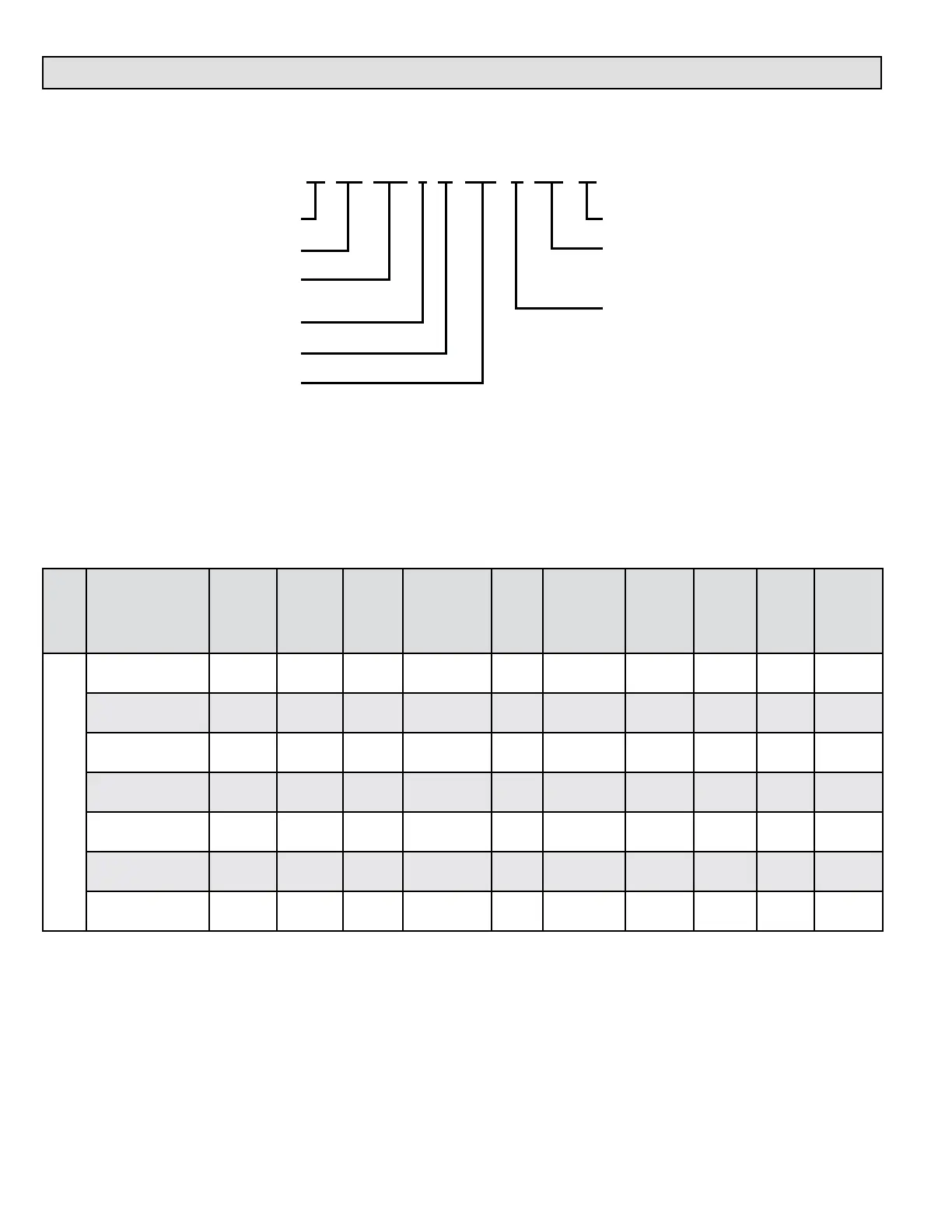
MODEL NUMBER GUIDE
Numeric Code
12 = 3 Ton add on cooling
16 = 4 Ton add on cooling
20 = 5 Ton add on cooling
A = 14.5" Width
B = 17.5 Width
C = 21.0 Width
D = 24.5 Width
A = Flagship
80 = 80% Efficiency
UH = Upflow/Horizontal
DF = Downflow
1 = 1 Stage
E = High Efficency Motor
Heating Input x 1000
A 80 UH 1 E 110 C 20 01
PHYSICAL AND ELECTRICAL DATA
Model
Input
(Btuh)
Output
(Btuh)
AFUE
(ICS)
Nom.
Cooling
Capacity
Gas
Inlet
(in.)
Volts/
Hz/
Phase
Max.
Time
Delay
Breaker
or Fuse
Nominal
F.L.A.
Trans.
(V.A.)
Approx.
Shipping
Weight
(lbs.)
Upow / Horizontal
A80UH1E045A12 44,000 36,000 80.00% 1-1/2 — 3 1/2 120-60-1 15 6.8 40 111
A80UH1E070A12 66,000 53,000 80.00% 1-1/2 — 3 1/2 120-60-1 15 6.8 40 111
A80UH1E070B12 66,000 53,000 80.00% 1-1/2 — 3 1/2 120-60-1 15 6.8 40 127
A80UH1E090B16 88,000 72,000 80.00% 2-1/2 — 4 1/2 120-60-1 15 8.4 40 142
A80UH1E090C20 88,000 72,000 80.00% 3 — 5 1/2 120-60-1 15 10.9 40 152
A80UH1E110C20 110,000 90,000 80.00% 4 — 5 1/2 120-60-1 15 10.9 40 160
A80UH1E135D20 132,000 107,000 80.00% 4 — 5 1/2 120-60-1 15 10.9 40 178
Note: For vent sizing and clearances to combustibles, please reference installation instructions.