508031-02 Issue 2135 Page 17 of 29
Gas Piping
Gas supply piping should not allow more than 0.5” w.c.
drop in pressure between gas meter and unit. Supply gas
pipe must not be smaller than unit gas connection.
Compounds used on gas piping threaded joints should be
resistant to action of liqueed petroleum gases.
Testing Gas Piping
If a exible gas connector is required or allowed by
the authority that has jurisdiction, black iron pipe shall
be installed at the gas valve and extend outside the
furnace cabinet.
CAUTION
In case emergency shutdown is required, turn o the
main shut-o valve and disconnect the main power to
unit. These controls should be properly labeled by the
installer.
IMPORTANT
Do not over torque (800 in-lbs) or under torque (350
in-lbs) when attaching the gas piping to the gas valve.
WARNING
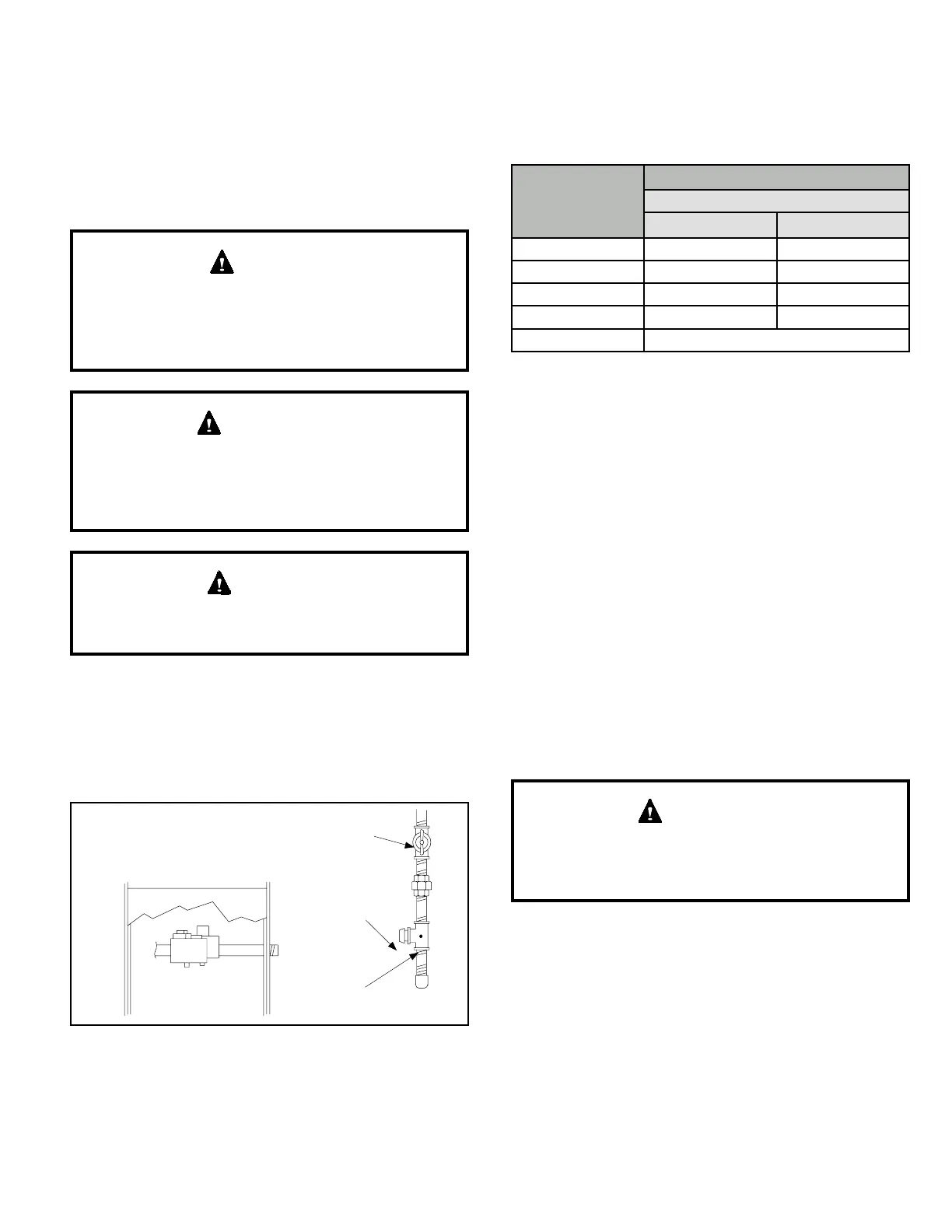
When pressure testing gas lines, the gas valve must be
disconnected and isolated. Gas valves can be damaged if
subjected to more than 0.5 psig (14” w.c.). See Figure 17.
If the pressure is equal to or less than 0.5 psig (14” w.c.),
close the manual shut-o valve before pressure testing to
isolate furnace from gas supply.
MANUAL MAIN SHUT-OFF VALVE
WILL NOT HOLD TEST PRESSURE
IN EXCESS OF 0.5 PSIG (14”W.C.)
GAS VALVE
CAP
FIELD PROVIDED
LINE PRESSURE TAP
Figure 17. Gas Piping Test Procedure
When checking piping connections for gas leaks, use
preferred means. Kitchen detergents can cause harmful
corrosion on various metals used in gas piping. Use of a
specialty Gas Leak Detector is strongly recommended.
Do not use matches, candles, ame or any other source of
ignition to check for gas leaks.
Gas Pressure Adjustment
Gas Flow (Approximate)
Model
Seconds for One Revolution
Natural Gas
1 cu ft Dial 2 cu ft Dial
-040 90 180
-060 60 120
-080 45 90
-100 36 72
Natural - 1000 btu/cu ft
Table 9. Gas Meter Clocking Chart
Furnace should operate at least 5 minutes before checking
gas ow. Determine time in seconds for two revolutions of
gas through the meter. (Two revolutions assures a more
accurate time.) Divide by two and compare to time in
Table 9. If manifold pressure matches Table 10 and rate is
incorrect, check gas orices for proper size and restriction.
Remove temporary gas meter if installed.
NOTE: To obtain accurate reading, shut o all other gas
appliances connected to meter.
Supply and Manifold Pressure
Supply Pressure Measurement
A port on the inlet side of the gas valve provides access to
the supply pressure tap. Loosen the screws and connect
a manometer to measure supply pressure. The minimum
supply line pressure is 4.5” - 13.0” w.c. for natural and 11.0
- 13.0” w.c. for LP/Propane. Tighten after measurements
have been taken.
For safety, shut unit o and remove manometer as soon
as an accurate reading has been obtained. Take care to
replace pressure tap plug.
IMPORTANT
Manifold Pressure Measurement
To correctly measure manifold pressure, follow the steps
below.
1. Remove the threaded plug from the outlet side of the
gas valve and install a eld-provided barbed tting.
Connect measuring device “+” connection to barbed
tting to measure manifold pressure.
Start unit and allow 5 minutes for unit to reach steady
state.


 To Next Page