508031-02Issue 2135Page 16 of 29
4. Reconnect the two harnesses to the motor control
module.
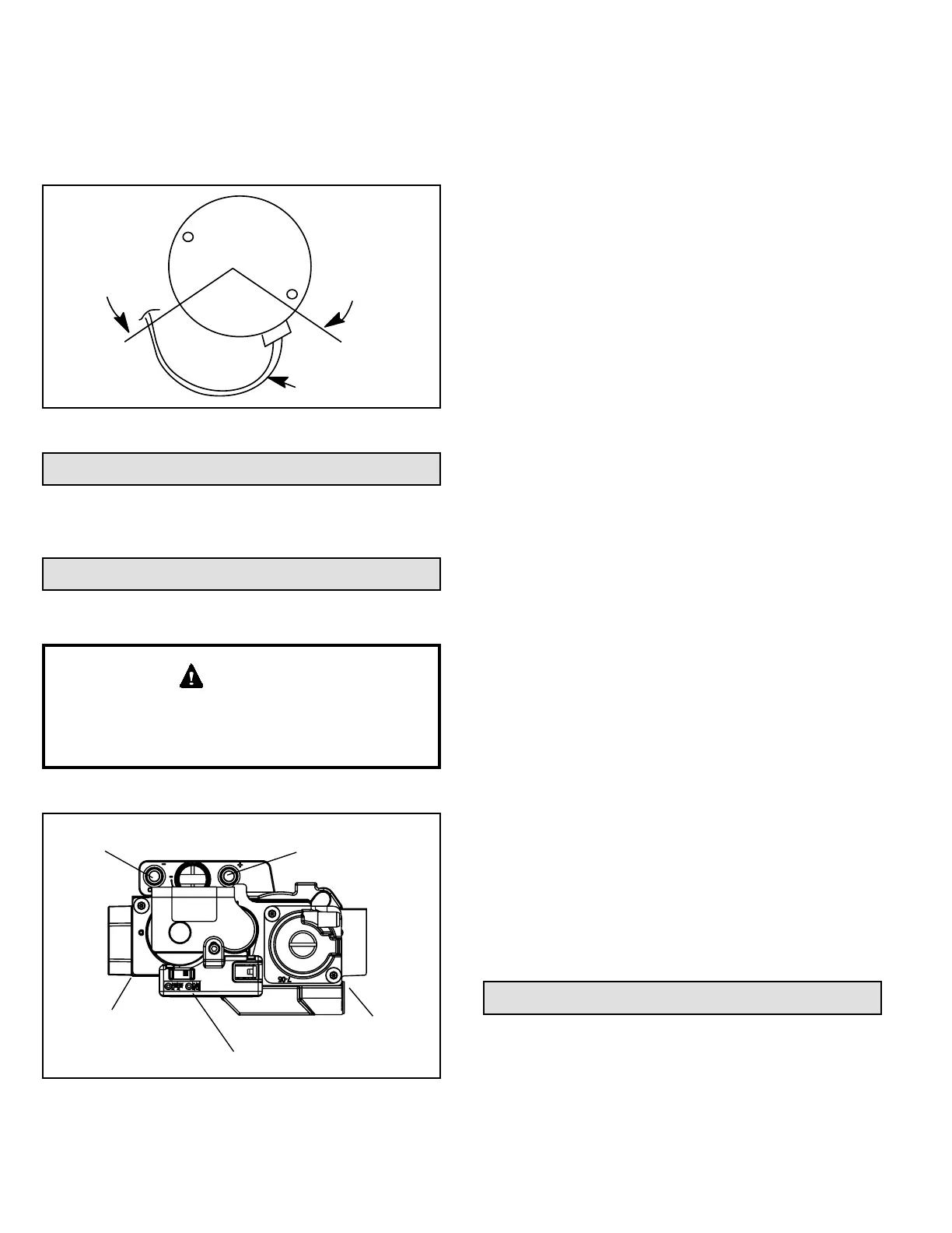
5. The electrical connectors of the motor should be
facing down to form a drip loop (Figure 15). This will
directs moisture away from the motor and its electric
connections on the motor.
CONNECTOR
ORIENTATION
BETWEEN 4 AND 8
O'CLOCK
BACK OF CONTROL
MODULE
DRIP LOOP
Figure 15. Drip Loop
Placement and Installation
Make sure unit is installed in accordance with installation
instructions and applicable codes.
Start-Up
Heating Start-Up
Shock and burn hazard.
A80UH1EX & 80G1UHEX units are equipped with a hot
surface ignition system. Do not attempt to light manually.
WARNING
Gas Valve Operation
Figure 16. Gas Valve
NEGATIVE AIR
PRESSURE PORT
POSITIVE AIR
PRESSURE PORT
MANIFOLD
PRESSURE TAP
INLET OUTLET
SUPPLY
PRESSURE
TAP
GAS VALVE SHOWN IN THE ON POSITION
1. STOP! Read the safety information at the beginning
of this section.
2. Set the thermostat to the lowest setting.
3. Turn o all electrical power to the unit.
4. This furnace is equipped with an ignition device which
automatically lights the burners. Do not try to light the
burners by hand.
5. Remove the upper access panel.
6. Move gas valve switch to OFF position. Do not force.
See Figure 16.
7. Wait ve minutes to clear out any gas. If you then
smell gas, STOP! Immediately call your gas supplier
from a neighbor’s phone. Follow the gas supplier’s
instructions. If you do not smell gas go to next step.
8. Move gas valve switch to ON position. Do not force.
See Figure 16.
9. Replace the upper access panel.
10. Turn on all electrical power to the unit.
11. Set the thermostat to desired setting.
NOTE: When unit is initially started, steps 1 through
11 may need to be repeated to purge air from gas line.
12. If the appliance will not operate, follow the instructions
“Turning O Gas to Unit” and call the gas supplier.
Turning O Gas to Unit
1. Set the thermostat to the lowest setting.
2. Turn o all electrical power to the unit if service is to
be performed.
3. Remove the upper access panel.
4. Move gas valve switch to OFF position. Do not force.
See Figure 16.
5. Replace the upper access panel.
Safety or Emergency Shutdown
Disconnect main power to unit. Close manual and main
gas valves.
Extended Period Shutdown
Turn o thermostat or set to “UNOCCUPIED” mode.
Close all gas valves (both internal and external to unit) to
guarantee no gas leaks into combustion chamber. Turn
o power to unit. All access panels and covers must be in
place and secured.
Heating System Service Checks
C.S.A. Certication
All units are C.S.A. design certied without modications.
Refer to the A80UH1EX & 80G1UHEX Installation
Instruction.


 To Next Page