508031-02 Issue 2135 Page 19 of 29
Proper Ground and Voltage
A poorly grounded furnace can contribute to poor ame
sense signal. Use the following procedure to check for
ground and voltage to the integrated control.
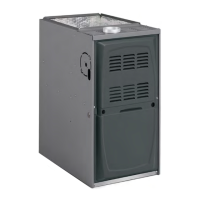
1. Measure the AC voltage between Line Neutral (spade
terminals) and “C” terminal (low voltage terminal
block) on the integrated control. See Figure 18. A wide
variation in the voltage between Line Neutral and “C”
as a function of load indicates a poor or partial ground.
Compare the readings to Table 13. If the readings
exceed the maximum shown in Table 13, make repairs
before operating the furnace.
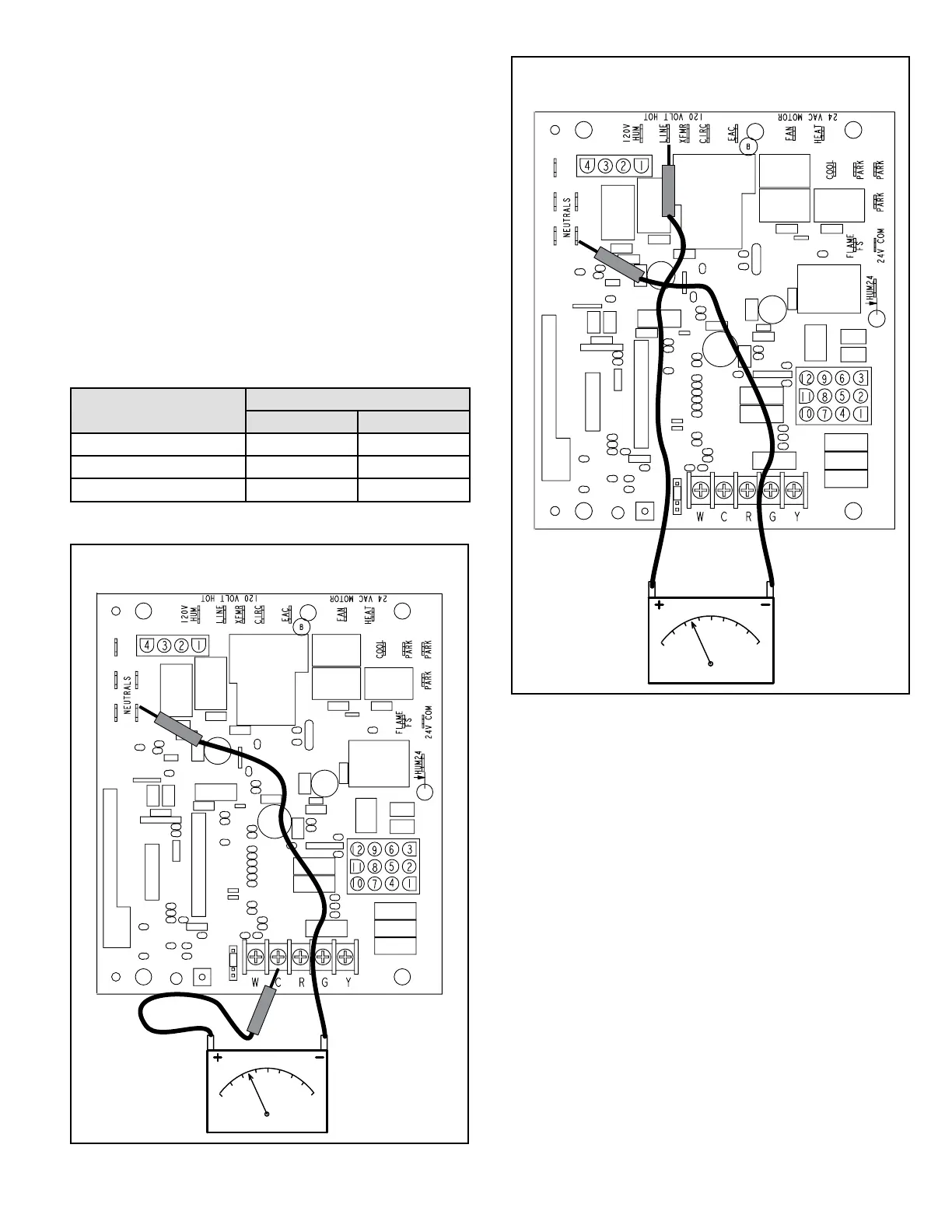
2. In addition, measure the AC voltage from Line Hot
to Line Neutral (spade terminals) on the integrated
control. See Figure 19. This voltage should be in the
range of 97 to 132 VAC.
Furnace Status
Measurement VAC
Expected Maximum
Power On Furnace Idle 0.3 2
CAI / Ignitor Energized 0.75 5
Indoor Blower Energized Less than 2 10
Table 13.
CHECK VOLTAGE BETWEEN LINE NEUTRAL
AND LOW VOLTAGE “C” TERMINAL
Figure 18.
CHECK VOLTAGE BETWEEN LINE HOT
AND LINE NEUTRAL
Figure 19.


 To Next Page