508033-02 Issue 2135 Page 29 of 48
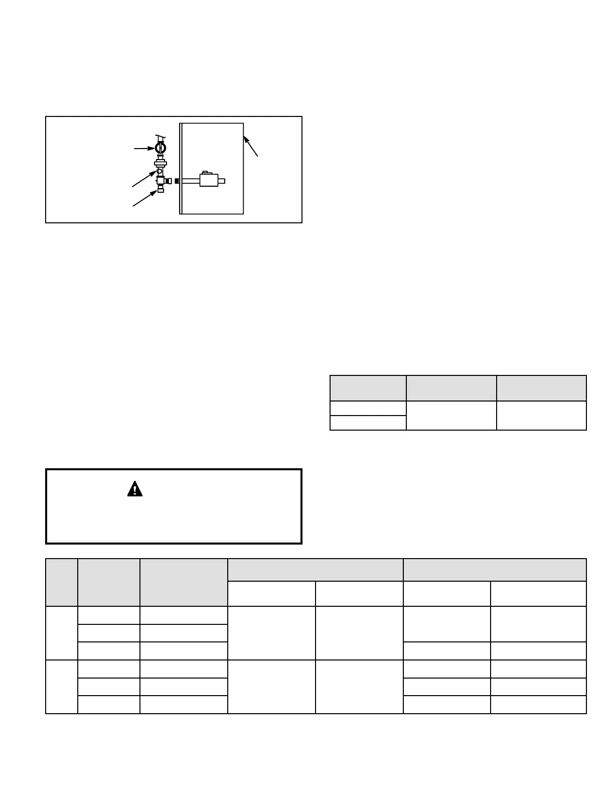
When pressure testing gas lines, the gas valve must be
disconnected and isolated. Gas valves can be damaged
if subjected to more than 0.5 psig (14” W.C.). See Figure
17. If the pressure is greater than 0.5psig (14”W.C.), use
the manual shut-o valve before pressure testing to isolate
furnace from gas supply.
MANUAL MAIN
SHUT-OFF VALVE
WILL NOT HOLD
NORMAL TEST
PRESSURE
CAP
ISOLATE
GAS VALVE
FURNACE
1/8 NPT PLUG
Figure 17.
When checking piping connections for gas leaks, use
preferred means. Kitchen detergents can cause harmful
corrosion on various metals used in gas piping. Use of a
specialty Gas Leak Detector is strongly recommended. It
is available under part number 31B2001. See Corp. 8411-
L10, for further details.
Do not use matches, candles, ame or any other
source of ignition to check for gas leaks.
Testing Gas Supply Pressure
A port on the inlet side of the gas valve provides access to
the supply pressure tap. See Figure 16. Loosen the screw
and connect a manometer to measure supply pressure.
The minimum supply line is 4.5” w.c. And the maximum
supply line is 13.0” w.c. Tighten screw after measurements
have been taken.
For safety, connect a shut-o valve between the
manometer and the gas tap to permit shut o of gas
pressure to the manometer.
IMPORTANT
Rate Check
Manifold Pressure Measurement
To correctly measure manifold pressure, follow the steps
below:
1. Remove the threaded plug from the outlet side of the
gas valve and install a eld-provided barbed tting.
Connect measuring device “+” connection to barbed
tting to measure manifold pressure.
2. Start unit on low heat and allow 15 minutes for unit to
reach steady state.
3. After allowing unit to stabilize for 15 minutes, record
manifold pressure and compare to value given in
Table 18.
4. Repeat on high heat.
5. Shut unit o and remove manometer as soon as an
accurate reading has been obtained. Take care to
remove barbed tting and replace threaded plug.
6. Start unit and perform leak check. Seal leaks if found.
Proper Combustion
Furnace should operate minimum 15 minutes with correct
gas ow rate before checking combustion. Take combustion
sample beyond the ue outlet. Table 17 shows acceptable
combustion for ALL A80US2VX models. The maximum
carbon monoxide reading should not exceed 100 ppm.
Firing Rate CO
2
% for Nat
CO
2
% for LP /
Propane
High Fire
6.0 - 7.5 7.5 - 9.0
Low Fire
Table 17.
Altitude
Unit LP Kit
Natural LP / Propane
HIgh Fire
in. w.c.
Low Fire
in. w.c.
HIgh Fire
in. w.c.
Low Fire
in. w.c.
0 - 4,500 ft.
060 20P40
3.0 - 3.8 1.3 - 1.7
3.4 - 3.8 1.5 - 1.9
080 20P41
100 n/a n/a n/a
4,501 -
7,500 ft.
060 20P40
2.5 - 3.3 1.3 - 1.7
2.7 - 3.2 1.3 - 1.7
080 n/a n/a n/a
100 n/a n/a n/a
Table 18. Supply Line and Manifold Pressure
(inches w.c.)