508107-01 Issue 2041 Page 5 of 58
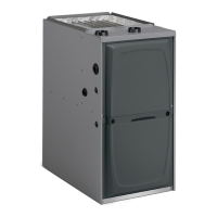
Technical Specications - 92G1UHE
PHYSICAL AND ELECTRICAL DATA
Model
Input
(Btuh)
Output
(Btuh)
AFUE
(ICS)
Nominal
Cooling
Capacity
Gas
Inlet
(in.)
Volts/
Hz/
Phase
Max.
Time
Delay
Breaker
or Fuse
Nominal
F.L.A.
Trans.
(V.A.)
Approx.
Shipping
Weight
(lbs.)
Upow/Horizontal
92G1UH030BE12 30000 29000 92.1% 1.5 - 3 1/2 120 - 60 - 1 15 6.8 40 121.5
92G1UH045BE12 44000 42000 92.1% 1.5 - 3 1/2 120 - 60 - 1 15 6.8 40 121.5
92G1UH070BE12 66000 63000 92.1% 1.5 - 3 1/2 120 - 60 - 1 15 6.8 40 128.5
92G1UH090BE12 88000 84000 92.1% 1.5 - 3 1/2 120 - 60 - 1 15 6.8 40 145.0
92G1UH090CE16 88000 84000 92.1% 2.5 - 4 1/2 120 - 60 - 1 15 8.4 40 145.0
92G1UH110CE16 110000 104000 92.1% 2.5 - 4 1/2 120 - 60 - 1 15 8.4 40 157.0
92G1UH110CE20 110000 105000 92.1% 3 - 5 1/2 120 - 60 - 1 15 10.9 40 159.0
Note: For vent length and clearances to combustibles, please reference installation instructions.
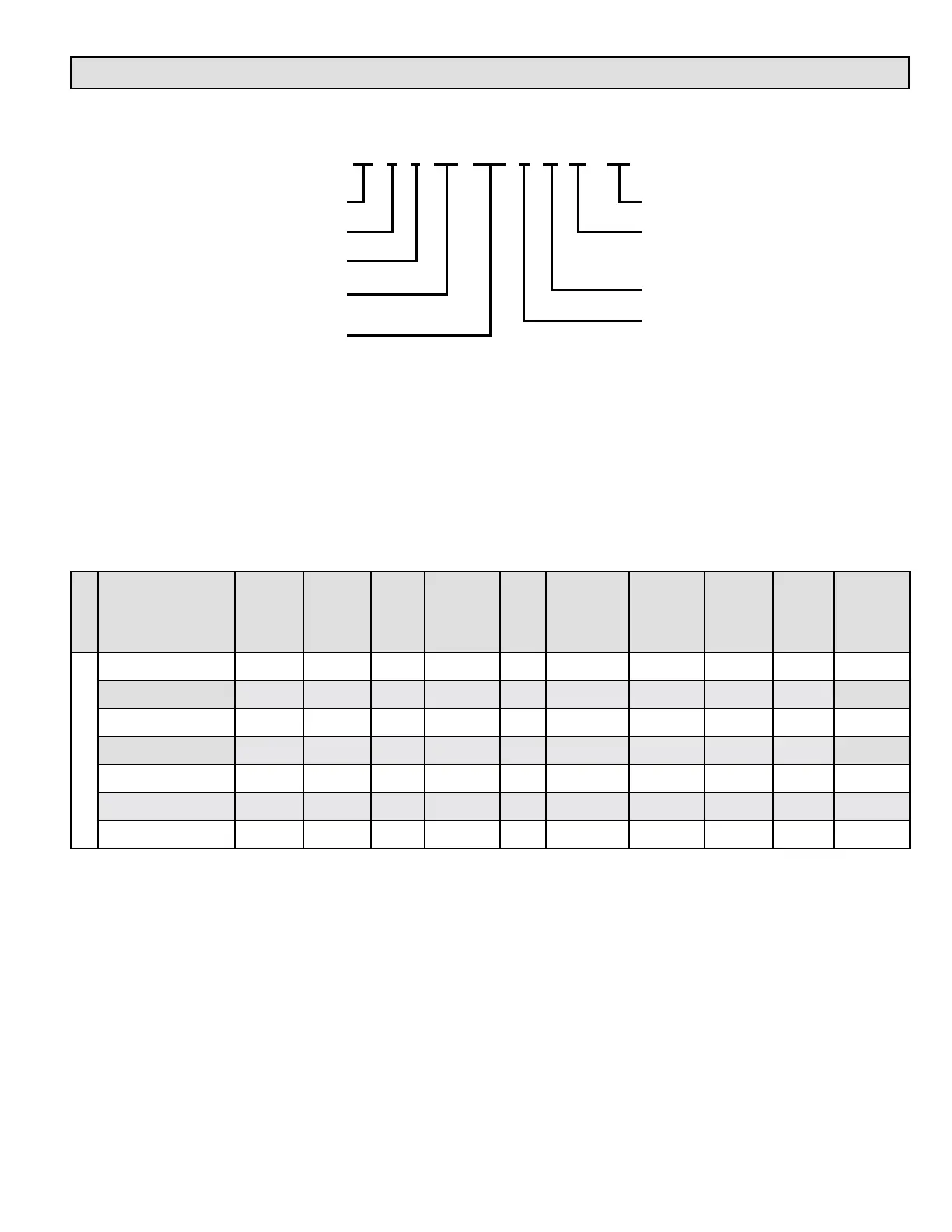
MODEL NUMBER GUIDE
Major Revision
12 = 3 Ton add on cooling
16 = 4 Ton add on cooling
20 = 5 Ton add on cooling
E = High Efficency
B = 17.5” width
C = 21.0” width
92 = 92% Efficency
Gas
1 = 1 Stage
UH = Upflow/Horizontal
DF = Downflow
Heating Input x 1000
92 G 1 UH 070 B E 12 -01