Do you have a question about the Allied A93UH1E and is the answer not in the manual?
Explains the model number nomenclature for A93UH1E units.
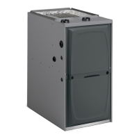
Provides detailed physical and electrical specifications for A93UH1E models.
Explains the model number nomenclature for 92G1UHE units.
Provides detailed physical and electrical specifications for 92G1UHE models.
Details precautions for handling electronic components to prevent electrostatic discharge damage.
Describes transformer, door interlock switch, and integrated control within the control box.
Explains the function and features of the hot surface ignition control system.
Covers ignitors, flame sensors, limit switches, and related components.
Details gas valve operation, manifold pressure measurement, and related tests.
Explains the role of the combustion air inducer and header box in airflow.
Details the function of the pressure switch and provides troubleshooting steps.
Describes the function and operation of the secondary limit control in the blower compartment.
Provides procedures for testing and installing the blower motor module.
Outlines approved materials and procedures for vent pipe and fitting installation.
Covers general venting practices, wall thickness, and exhaust piping routing.
Provides guidelines for selecting and installing vent piping systems.
Details minimum and maximum allowable vent pipe lengths based on capacity and elbows.
Describes typical exhaust and intake pipe connection methods and requirements.
Specifies required clearances for vent terminals based on installation type and location.
Details the installation and priming procedures for the condensate trap and drain.
Outlines pre-start checks for electrical, condensate traps, and gas systems.
Guides on safely starting the furnace for heating operation and gas valve use.
Explains the steps to properly prime the condensate trap before operation.
Lists common issues and checks when the furnace fails to operate.
Details procedures for testing gas piping and supply pressure.
Covers checking CO2 levels and ensuring proper combustion for optimal performance.
Explains necessary adjustments for furnaces installed at high altitudes.
Details procedures for checking furnace grounding and voltage supply.
Explains blower speed adjustment and external static pressure measurement.
Covers regular tasks like filter replacement and checking vent pipes.
Provides detailed steps for cleaning the furnace's heat exchanger.
Provides a flowchart for diagnosing heating operation issues using LED codes.
Provides a flowchart for diagnosing cooling operation issues using LED codes.
Explains the sequence of operation for continuous fan and accessory modes.
| Brand | Allied |
|---|---|
| Model | A93UH1E |
| Category | Air Handlers |
| Language | English |