508107-01 Issue 2041 Page 13 of 58
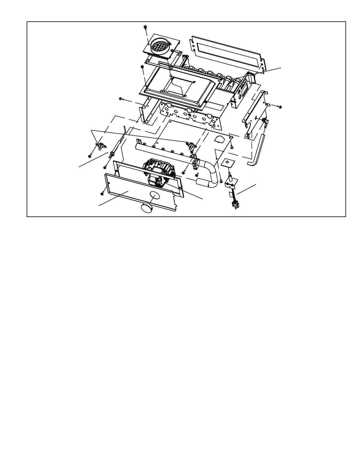
Figure 5. Burner Box Assembly
Gas Valve
Burner Box Front
Rollout Switch(s)
Flame Sensor
Ignitor
Burner Assembly
Flame Rollout Switches (Figure 5)
Flame rollout switches S47 are SPST N.C. high temperature
limits located on the left and right of the front buner box
plate. S47 is wired to the burner ignition control A92. When
either of the switches sense ame rollout (indicating a
blockage in the combustion passages), the ame rollout
switch trips, and the ignition control immediately closes
the gas valve. Switch S47 in all A93UH1E / 92G1UHE
units is factory preset to open at 210 F + 12 F (99 C +
6.7 C) on a temperature rise. All ame rollout switches are
manual reset. See ash code 8 in Table 4 or Table 5 for
troubleshooting.
Flame Sensor (Figure 5)
A ame sensor is located on the left side of the burner
support. The sensor is mounted on the front burner box
plate and the tip protrudes into the ame envelope of the
leftmost burner. The sensor can be removed for service
(use steel wool only to clean) without removing any part of
the burners. During operation, ame is sensed by current
passed through the ame and sensing electrode. The
ignition control allows the gas valve to remain open as long
as ame signal is sensed.
NOTE: The A93UH1E / 92G1UHE is polarity sensitive.
Make sure that the furnace is wired correctly and is properly
grounded.
A microamp DC meter is needed to check the ame signal
on the integrated control.
Flame (microamp) signal is an electrical current which
passes from the integrated control to the sensor during
unit operation. Current passes from the sensor through the
ame to ground to complete a safety circuit.
Heat Exchanger (Figure 6)
A93UH1E / 92G1UHE units use an aluminized steel primary
and stainless steel secondary heat exchanger assembly.
Heat is transferred to the air stream from all surfaces of the
heat exchanger. The shape of the heat exchanger ensures
maximum eciency.
The combustion air inducer pulls fresh air through the
burner box. This air is mixed with gas in the burners. The
gas / air mixture is then burned at the entrance of each
clamshell. Combustion gases are then pulled through the
primary and secondary heat exchangers and exhausted
out the exhaust vent pipe.
 Loading...