507270-03Page 28 of 60 Issue 1621
Details of Intake and Exhaust Piping Terminations for
Direct Vent Installations
NOTE: In Direct Vent installations, combustion air is taken
from outdoors and ue gases are discharged to outdoors.
NOTE: Flue gas may be slightly acidic and may adversely
affect some building materials. If any vent termination
is used and the ue gases may impinge on the building
material, a corrosion-resistant shield (minimum 24 inches
square) must be used to protect the wall surface. If the
optional tee is used, the protective shield is required.
The shield should be constructed using wood, plastic,
sheet metal or other suitable material. All seams, joints,
cracks, etc. in the affected area should be sealed using an
appropriate sealant. See Figure 37.
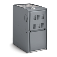
Intake and exhaust pipes may be routed either horizontally
through and outside wall or vertically through the roof. In
attic or closet installations, vertical termination through
the roof is preferred. Figures 33 through 43 show typical
terminations.
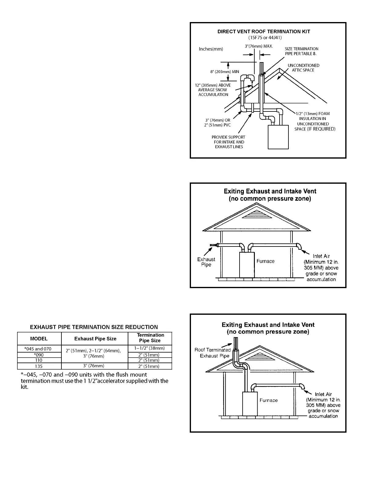
1. Intake and exhaust terminations are not required to be
in the same pressure zone. You may exit the intake on
one side of the structure and the exhaust on another
side (Figure 34). You may exit the exhaust out the roof
and the intake out the side of the structure (Figure 35).
2. Intake and exhaust pipes should be placed as close
together as possible at termination end (refer to
illustrations). Maximum separation is 3” (76 mm) on roof
terminations and 6” (152 mm) on sidewall terminations.
3. On roof terminations, the intake piping should terminate
straight down using two 90° elbows (See Figure 33).
4. Exhaust piping must terminate straight out or up as
shown. A reducer may be required on the exhaust piping
at the point where it exits the structure to improve the
velocity of exhaust away from the intake piping. See
Table 8.
NOTE: Care must be taken to avoid recirculation of exhaust
back into intake pipe.
Figure 35
Table 8
Figure 33
Figure 34