Allied Construction Products, LLC www.alliedcp.com
SOM576701_14jan
25
9.0 Attach / Remove Breaker From Carrier –
[cont’d]
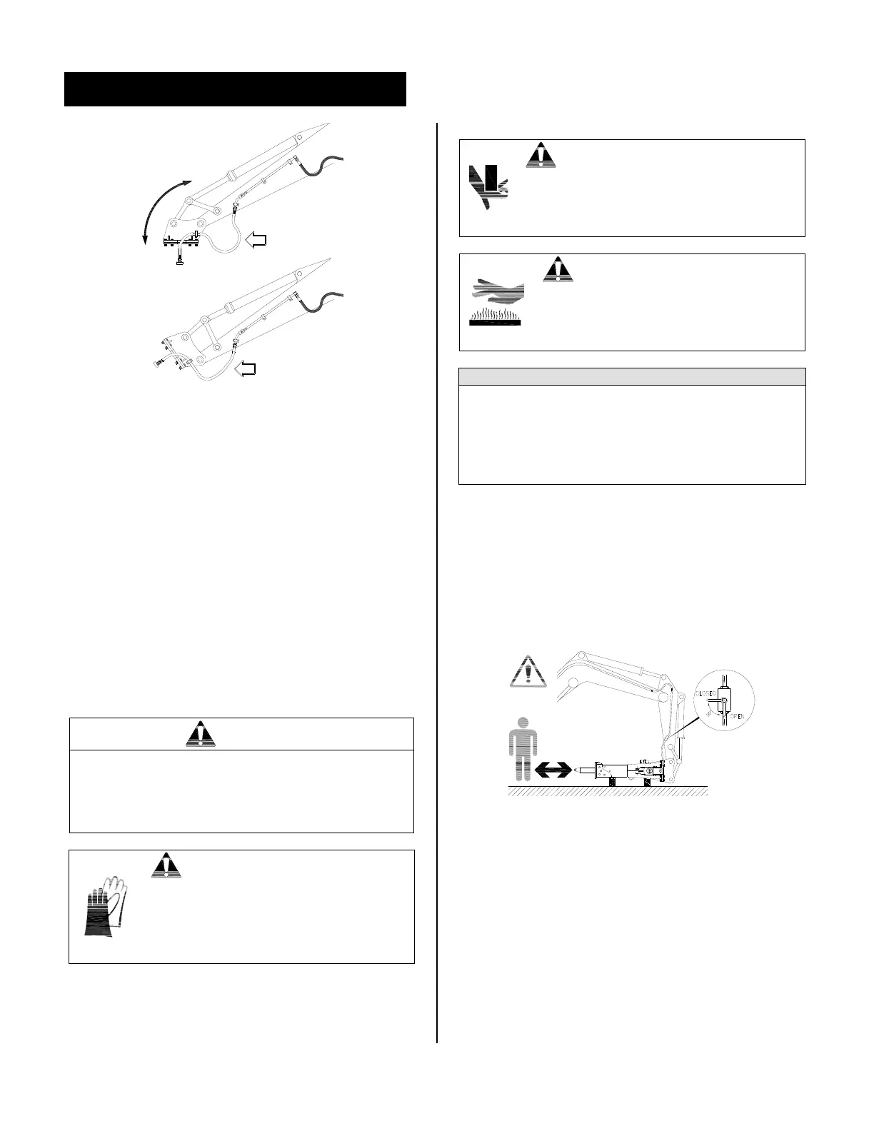
Fig. 9-5 Hose routing must be free of interference
and length restrictions
9.6 Remove Breaker from the Carrier
9.3 Tools Required to Remove the Breaker
No special tools are required, but the following tools
should be available:
PPE including safety eyewear & gloves
Sledge Hammer
Drift pin
3/4 drive socket wrench
3/4 drive metric sockets
Standard and Metric open end wrenches
Pry bar
Rags and fluid collection container
CAUTION
Some procedures, such as attaching the Breaker to
and from the carrier will require an assistant. Both
the operator and assistant must be qualified in
these procedures. All directions and signals must
be agreed upon in advance.
CAUTION
Protect hands, feet and other body parts
against injury. When handling
equipment, PPE must include
appropriate clothing, gloves, safety
eyewear and shoes.
CAUTION
Crush injury. Keep hands, feet and other
body parts clear of crush points. Use
sufficient blocking and restraints to avoid
accidental or sudden movement of loads.
CAUTION
Burn injury from contact with hot
surface. Some components become hot
during operation. Allow parts and fluids
to cool before handling.
IMPORTANT
Contamination can diminish service life. Always
clean area around fluid connections prior to opening
the hydraulic system. Collect all fluids in a suitable
container when opening the hydraulic system. Clean
up spills and obey all local regulations for the
disposal of these fluids.
1. Operator: Move carrier and breaker to a stable
and level surface. Position the Breaker
horizontally with the hose side up and the
breaker tool pointing toward the carrier.
2. Shut the carrier off and relieve the pressure in the
hydraulic tank and lines.
Fig. 9-6 Close Supply and Return Valves
3. Assistant: Check that the Breaker is stable and
all loads are supported. Close the supply and
return valves.
4. Clean dirt from connection areas. Disconnect the
hoses from the valves. Seal all connections with
the appropriate plugs and caps.
5. Remove keepers and pins. Collect any shims and
adapters, if used, and store them for future use.
6. See Section 8.0 for storage instructions.