Allied Construction Products, LLC www.alliedcp.com
SOM576701_14jan
45
14.0 Technical Information –[cont’d]
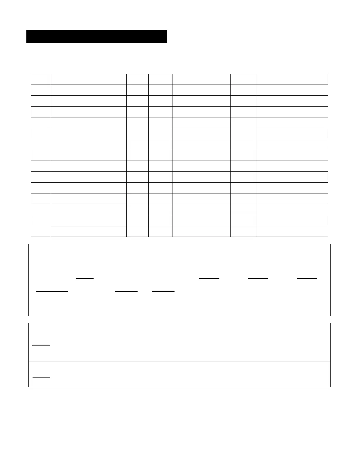
Table 14.4 Fastener Torque Model AR110C AR120B
Item Description Qty Size Ft-Lbs. [N·m] Size Ft-Lbs. [N·m]
9 Accum Top Bolt 8 370 [500] 480 [650]
11* Side Rod (Torque + Turn) 4 --- 370 [500] + 100º --- 370 [500] + 100º
43 Accum Bottom Bolt 12 M20 260 [350] M22 390 [530]
44 Gas Charge Bolt 1 M08 15 [20] M08 15 [20]
45 Flg Mtg Bolt [OUT] 4 M12 70 [130] M14 110 [150]
47 Flg Mtg Bolt [IN] 4 M10 45 [60] M12 70 [130]
48 Flg Plug 3 R1/4 24 [33] R1/4 24 [33]
49 Main Spool Cover Bolt 12 M14 175 [240] M16 103 [140]
53 Oper Valve Cover Bolt 4 M12 115 [160] M12 73 [100]
55 Flg Plug 1 R1/2 65 [90] R1/2 65 [90]
56 Flg Plug 2 R3/8 50 [70] R3/8 50 [70]
57 Flg Plug 1 R R
65 Check Valve Cover Bolt 4 M12 115 [160] M12 115 [160]
--- Top Mtg Brkt Bolts 14 M24 580 [800] M24 580 [800]
Table 14.5 Side Rod Tightening Item 11*
IMPORTANT! Apply Moly-Paste 676927 to threads before assembly.
Step 1 Level-1 Level-2 Level-3
Pre-torque Ft-Lbs. [N·m] AR110C AR120B
125 [165] 245 [330] 370 [500]
*Use progressive tightening technique to draw side rods up evenly. Torque the side rods* in diagonal
sequence (Fig 14-5), in small increments (Level 1, Level 2, Level 3), until torque level (3) is achieved.
Step 2
Apply heat evenly to
side rods
IMPORTANT! Do not over-heat the side rods. Excessive heat will
damage side rod beyond use. Do not exceed 390 F [200 C]. Heat until
side ride can be turned with hand wrench* and minimal effort applied. (*3/4"
drive and breaker bar)
Step 3
Final Torque + Turn º
Turn each side rod according to +º (or flats) shown in table. Follow
tightening sequence Fig 14-5. Use hand wrench only - Impact tools
prohibited!