Copyright © 1996 General Motors Corp. 6–27
REBUILD OF SUBASSEMBLIES
(6) Repeat Steps (2), (3), (4), and (5). When
the running clearance is within 0.0765–0.1265 inch
(1.944–3.213 mm), remove snapring 1, clutch back-
plate 2, clutch plates 3 and 4, and piston. Keep the
clutch plates together as a package until required.
c. Assembly (Foldout 9,A)
(1) If check ball 12 was removed, place the
new ball into the bore. Stake the bore at three equally
spaced locations. The bore is properly staked when the
ball has the minimum axial movement specified in Fig-
ure 6–45 and when the ball is retained by the staking
when a 30 lb (133 N) load is applied against the ball.
(2) Install sixteen return springs 7 (Foldout
9,A) into their pockets in piston 8. Install spring re-
tainer 6, recess side first, onto the springs.
(3) Place the clutch assembly in a press,
spring retainer upward. Lay snapring 5 in its approxi-
mate installed position, on spring retainer 6.
(4) Using compressor J 23616, compress the
spring retainer until it clears the snapring groove in the
housing hub (Figure 6–43). Install snapring 5 (Foldout
9,A) into the groove in the hub in clutch housing as-
sembly 11. Release the press and remove the clutch as-
sembly.
(5) Beginning with an external-tanged clutch
plate, install the clutch pack removed in Paragraph 6–
12b(6) or that which was determined in Paragraph 6–
17c.
(6) Install backplate 2, flat side first, onto the
clutch plates. Install snapring 1 to retain the backplate.
6–13. CENTER SUPPORT ASSEMBLY
a. Disassembly (Foldout 9,B)
(1) Remove pistons 9 and 18 with attached
parts, from center support assembly 13
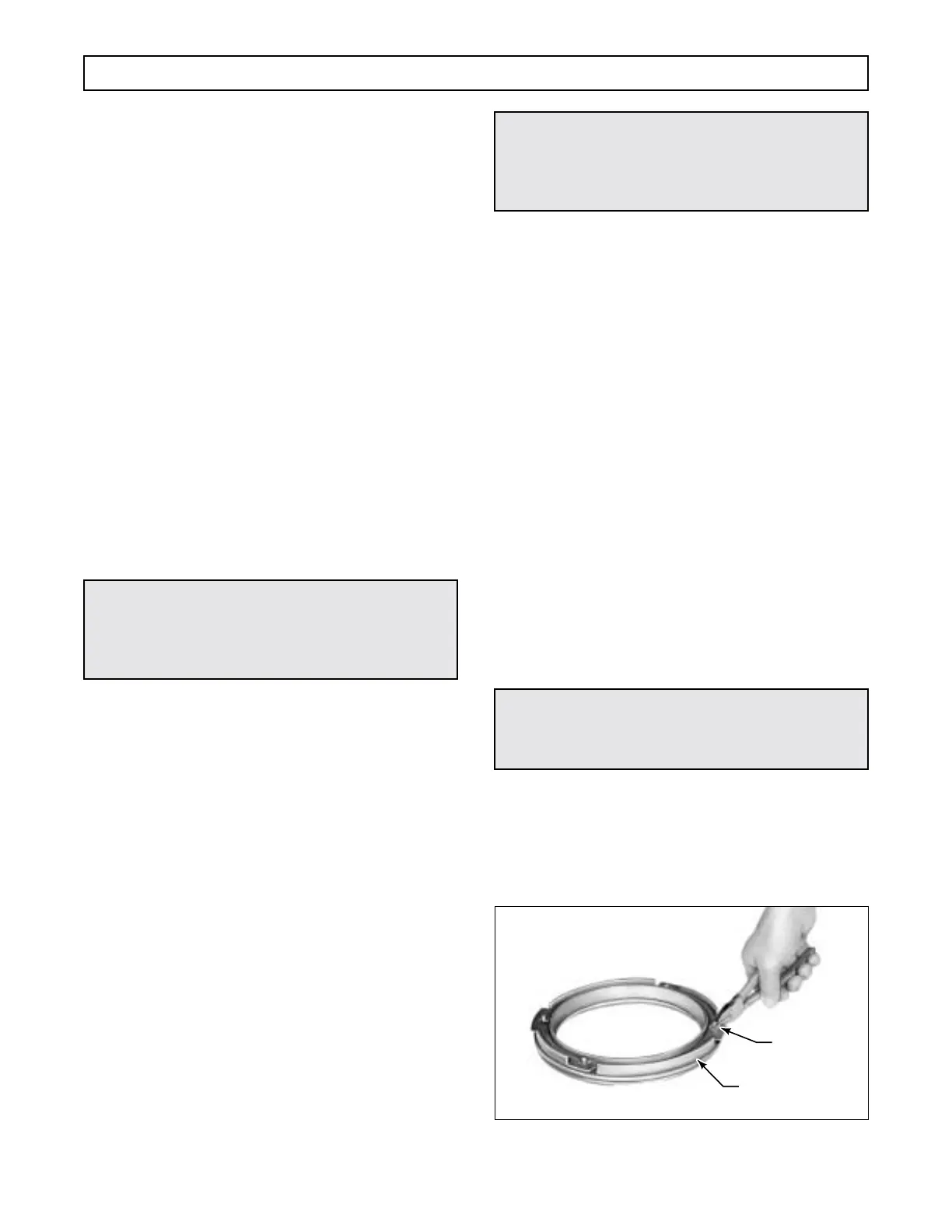
(2) Remove eight retainer washers 6 and 21,
(Figure 6–46).
(3) Remove spring retainers 7 and 20 (Fold-
out 9,B). Remove twenty-four piston return springs 8
and 19.
(4) Remove piston sealrings 10 and 11 from
piston 9.
(5) Remove piston sealrings 16 and 17 from
piston 18.
(6) Remove the two hook-type sealrings 12
from center support and bushing assembly 13.
(7) Insert, but do not force, rotating sealring
gauge J 29198-1 into the hub sealring grooves. Rotate
the gauge 360 degrees. If the gauge will not rotate
freely, the front support must be replaced.
(8) If bushing replacement is necessary,
place support and bushing assembly 13 in a press,
sealring grooves side upward. Press bushing 14 out of
the support.
Figure 6–46. Removing Self-Locking Retainer Washers
CAUTION:
When installing the fourth clutch snapring, do
not allow the spring retainer to catch in the
snapring groove.
CAUTION:
When removing piston retainer washers, cut the
retainer washers carefully to prevent damaging
the piston projections.
CAUTION:
When removing the center support bushing be
careful not to damage the bushing bore.
THIRD CLUTCH
PISTON
RETAINER
WASHER
H02260
 Loading...


