5–10 Copyright © 1996 General Motors Corp.
AT 500, 1500 SERIES AUTOMATIC TRANSMISSIONS
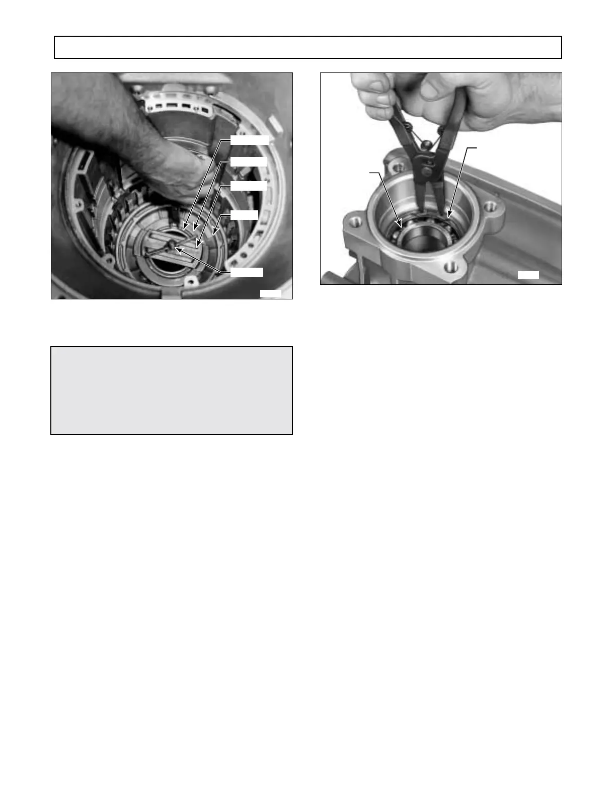
Figure 5–23. Removing First Clutch Spring
Retainer Snapring
(4) Remove the snapring. Remove the com-
pressor assembly.
(5) Remove the spring retainer and the
twenty-two piston return springs.
(6) Remove the first clutch piston (Figure
5–23). Remove the two lip-type sealrings from the
piston.
Figure 5–24. Removing Output Shaft Bearing Snapring
r. Removal of Output Shaft Seal and Bearing
(1) Rotate the transmission so that the output
is upward. Remove output seal 6 (Foldout 12,B) from
the rear of the transmission housing.
(2) Clean the bore from which the seal was
removed.
(3) Remove the snapring that retains the out-
put shaft bearing (Figure 5–24).
(4) Remove the bearing from its bore.
(5) Remove the transmission housing, with
its remaining attached parts, from the transmission
holding fixture. Refer to Paragraph 6–14 for rebuild of
the transmission housing.
WARNING!
When removing the first clutch snapring, do not
allow the spring retainer to catch in the snapring
groove. Failure to observe this warning may re-
sult in personal injury and damage to the spring
retainer.
H02910
SNAPRING
RETAINER
J 23630-02
J 23630-3
PISTON
 Loading...


