6–30 Copyright © 1996 General Motors Corp.
AT 500, 1500 SERIES AUTOMATIC TRANSMISSIONS
(9) Remove needle bearing assembly 32 and
bearing race 33 located between output shaft 45 and
rear sun gear 31.
(10) Place the output shaft on a work bench in
a vertical position (rear planetary carrier upward). If
necessary, force the planetary carrier downward until
snapring 35 is clear of the carrier. Remove the
snapring and bearing 44.
(11) Remove rear carrier assembly 36 from
the output shaft.
(12) On models before S/N 5071, remove the
spiral retainer ring 51 and thrust washer 52 that retain
rear planetary ring gear 53 to carrier assembly 36. Re-
move ring gear 53 and thrust washer 54. On models af-
ter S/N 5070, the ring gear is not included in the
planetary gear unit. Refer to Paragraph 6–16 for re-
build of the rear planetary carrier assembly.
(13) Remove spring pin 50. If bushing or plug
replacement is necessary, remove bushing 47 and ori-
fice plug 49 from output shaft 48.
(14) If bushing replacement is necessary, re-
move two bushings 2 from sun gear shaft 3.
b. Assembly (Foldout 10,A)
(1) If orifice plug 49 was removed from out-
put shaft 48, install a new plug. Press the plug clear of
the chamfer.
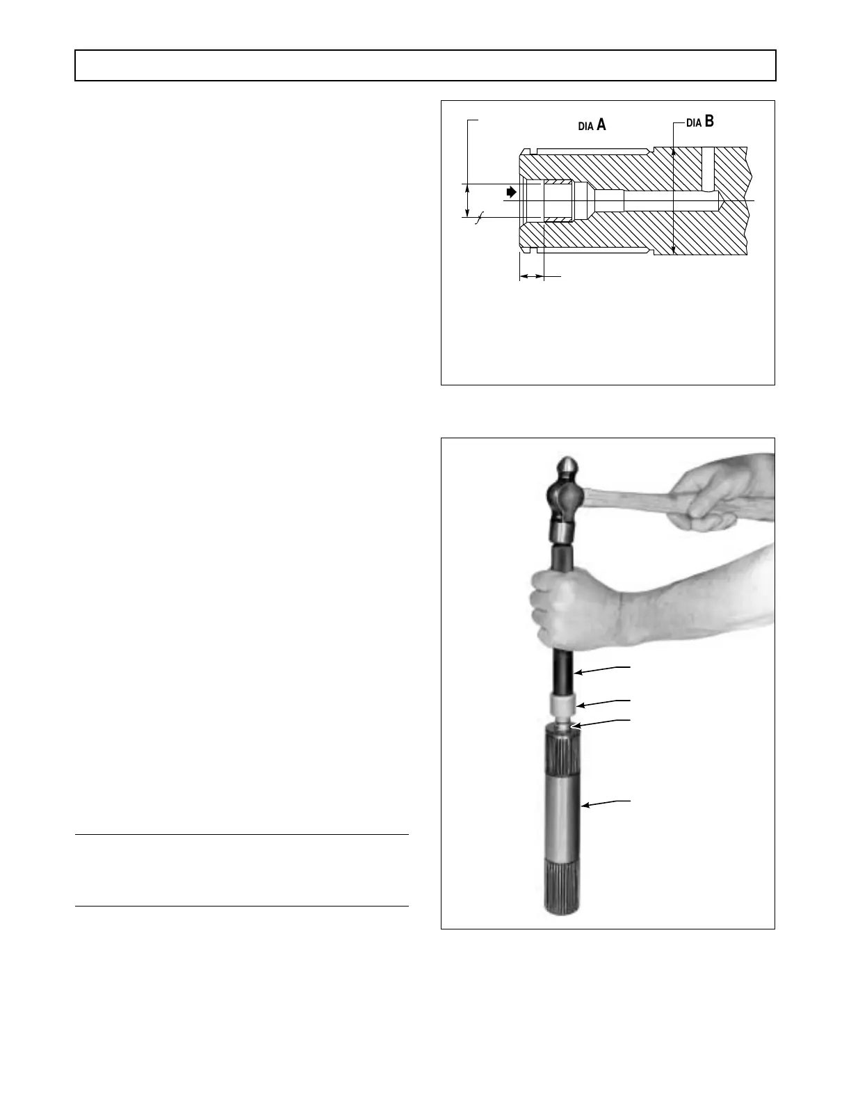
(2) If bushing 47 was removed, install a new
bushing into output shaft 48, following the specifica-
tions in Figure 6–51. Bushing installer tool J 24451
can be used along with driven handle J 8092 (Figure
6–52).
NOTE:
Do not use or reuse a sun gear shaft 3 that is drilled
for staked bushings.
(3) If bushings 2 were removed from sun
gear shaft 3, install new bushings, following the speci-
fications in Figure 6–53. Bushing installer tool
J 23614-A (for models without lockup) or J 39737 (for
models with lockup) can be used (Figure 6–54).
Figure 6–51. Output Shaft Assembly
Figure 6–52. Installing Output Shaft Bushing
(4) If bushing 15 was damaged or distorted,
refer to Paragraph 6–16c for machining instructions.
DIA B
DIA A
0.6485 in. (16.472 mm)
0.6475 in. (16.447 mm)
• When mounted on DIA A total runout of DIA B
to be within 0.002 in. (0.05 mm)
• Bushing must withstand approximately
350 LBS (1577 N) load in direction shown
0.370 in. (9.40 mm)
V02956
H02957
J 24451
J 8092
SHAFT
BUSHING
 Loading...


