ITA ENG FRA ESP DEU POR
3 / 12
6-1622241 rev.6 04/12/2018
Compatible from firmware version BIOS1BT04
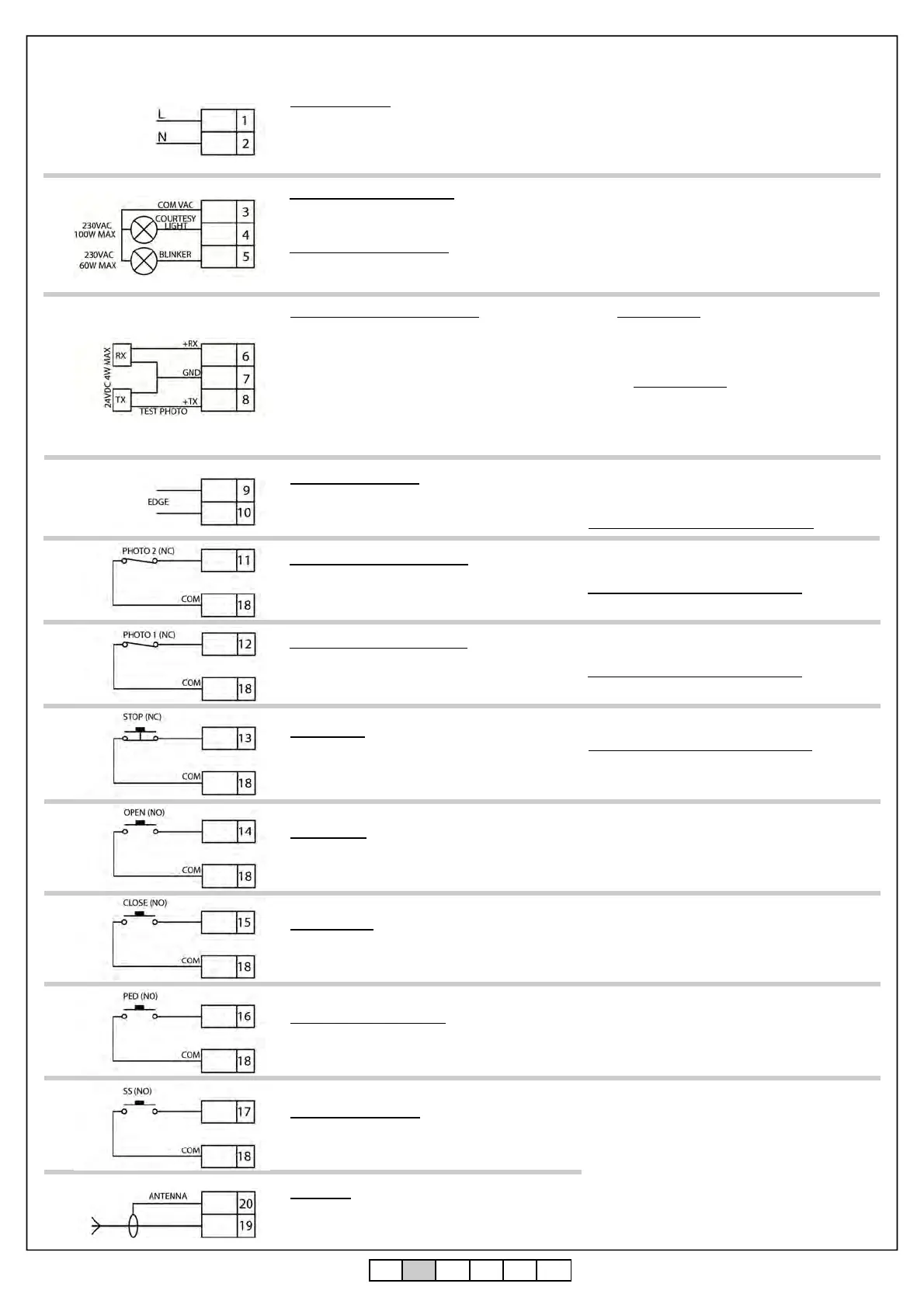
COURTESY LIGHT OUTPUT
Connect the courtesy light to the clamps 3 and
4, 230Vac 100W MAX.
FLASHING LIGHT OUTPUT
Connect the flashing light to the clamps 3 and
5.
It is possible to light up the action area of the
automatism during each motion.
The functioning of the auxiliary light is controlled in
the advanced menu FCY.
Use a flashing light without self flashing card
230Vac 60W MAX
PHOTOCELLS POWER SUPPLY
Connect the clamp 6 of the control unit to the
clamp + of the power supply of the photocells
receiver.
Connect the clamp 7 of the control unit to the
power supply clamp - of the photocells receiver
and of the transmitter.
Connect the clamp 8 of the control unit to the
power supply clamp of the trasnmitter of the
photocells.
The photocells test is activated in the advanced
menu tPh.
ATTENTION: the control unit gives a voltage of 24
Vdc and can supply a maximum power of 4W.
For the safety edge test connect the test device of
the safety edge on the power supply pins of the TX
(test activated wiht low logic signal 0Vdc).
Please refer to the manual of the safety edge.
SAFETY EDGE INPUT
Connect the safety edge contacts to the clamps
9 and 10 of the control unit.
Select the type of security edge used (mechanical
or 8K2) through the menu Edm, select the type of
functioning through the menuiEd.
If not used set the DIP switch EDGE ON.
OPENING PHOTOCELL INPUT
Connect the NORMALLY CLOSED contact
of the photocell (PHOTO 2) between the clamps
11 and 18 of the control unit.
The functioning of the opening photocell is
controlled in the advanced menu Ph2.
If not used set the DIP switch PH2 ON.
CLOSING PHOTOCELL INPUT
Connect the NORMALLY CLOSED contact
of the photocell (PHOTO 1) between the clamps
12 and 18 of the control unit.
The functioning of the closing photocell is controlled
in the advanced menu Sph.
If not used set the DIP switch PH1 ON.
STOP INPUT
Connect the NORMALLY CLOSED contact of
the STOP between the clamps 13 and 18 of the
control unit.
If not used set the DIP switch STOP ON.
OPEN INPUT
Connect the button OPEN between the clamps
14 and 18 of the control unit.
CLOSE INPUT
Connect the button CLOSE between the
clamps 15 and 18 of the control unit.
PARTIAL OPENING INPUT
Connect the button PED between the clamps
16 and 18 of the control unit.
STEP BY STEP INPUT
Connect the button SS between the clamps 17
and 18 of the control unit.
ANTENNA
Connect the signal cable of the antenna to the
clamp 19 and the ground of the antenna to the
clamp 20 of the control unit.
The presence of the metallic parts or humidity in the
walls could have negative influences on the range
of the system. We suggest therefore to not place
the receiving antenna and/or transmitters near big
metallic objects, near the floor or on the ground.
POWER SUPPLY
Connect the power supply cable between clamp
1 and 2 of the control unit
Power supply 230 Vac 50 Hz
Do not connect the card directly to the electric
network. Put a device which can ensure the
disconnection of each pole from the power supply of
the control unit.