ITA ENG FRA ESP DEU POR
12 / 12
www.remotecontrolgates.c
o.uk
rev.1
22/05/2015
Compatible from firmware version BIOS2BT02
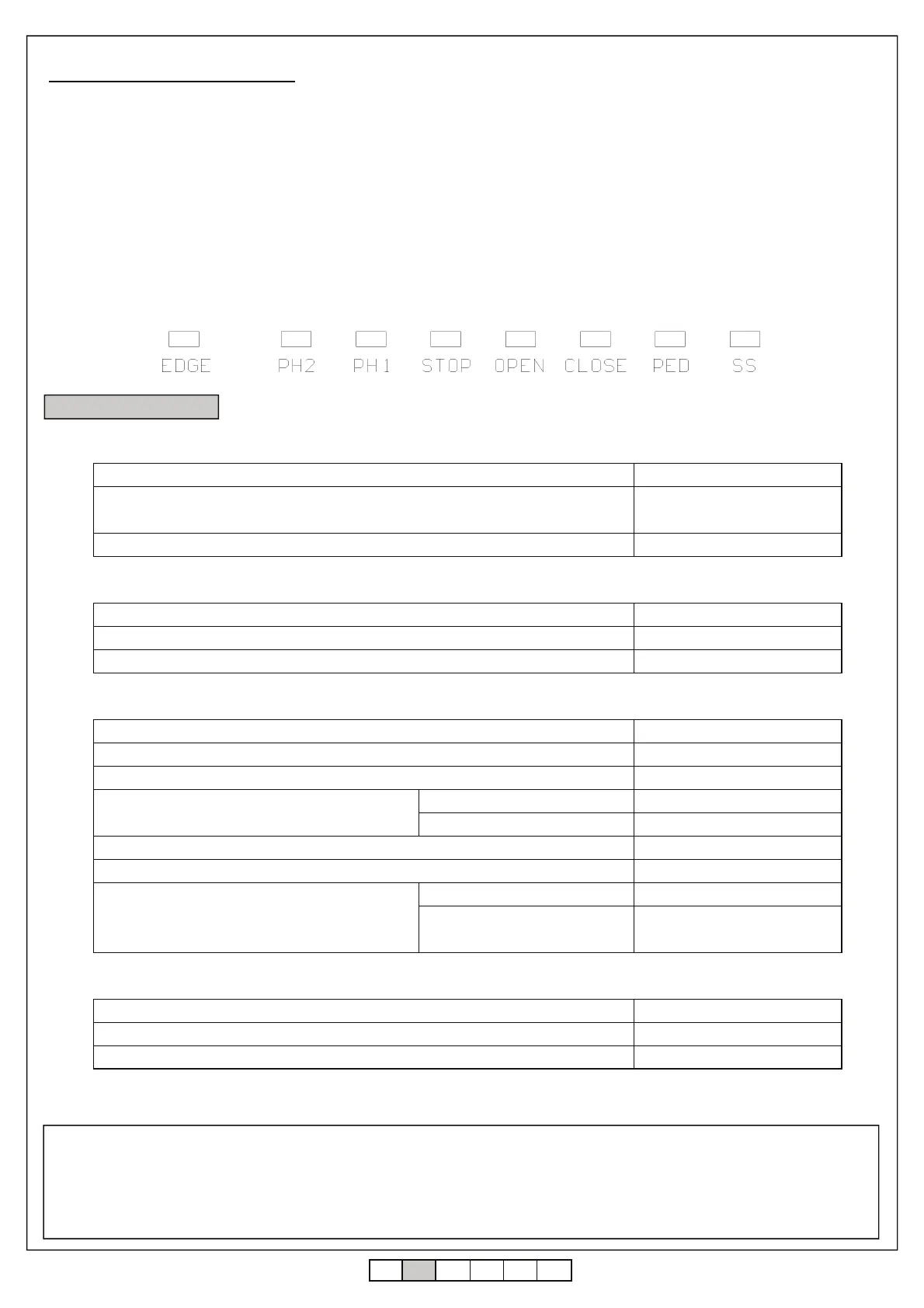
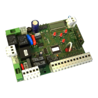
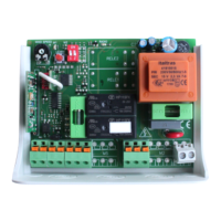
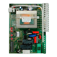
8. Technical features
7.3 Input LED and safety devices
RED (normally on)
RED (normally on)
RED (normally on)
RED (normally on)
GREEN (normally off)
GREEN (normally off)
GREEN (normally off)
GREEN (normally off)
GUARANTEE - In compliance with legislation, the manufacturer’s guarantee is valid from the date stamped on the product and is restricted to the
repair or free replacement of the parts accepted by the manufacturer as being defective due to poor quality materials or manufacturing defects. The
guarantee does not cover damage or defects caused by external agents, faulty maintenance, overloading, natural wear and tear, choice of incorrect
product, assembly errors, or any other cause not imputable to the manufacturer. Products that have been misused will not be guaranteed or repaired.
Printed specifications are only indicative. The manufacturer does not accept any responsibility for range reductions or malfunctions caused by
environmental interference. The manufacturer’s responsibility for damage caused to persons resulting from accidents of any nature caused by our
defective products, are only those responsibilities that come under Italian law.
POWER SUPPLY AND CONSUMPTION
Power supply voltage 230 Vac - 50/60 Hz
Absorption from line (Standby) 55mA @ 230 Vac
Standard configuration (2 couple of photocells, RX radio safety edge)
Line fuse F6.3A
MOTOR POWER SUPPLY
Number of motors 1 / 2
Motor power supply voltage 230 Vac - 50/60 Hz
Maximum power absorbed from motors 2 x 700W
ACCESSORIES POWER SUPPLY
Accessories power supply voltage 24Vdc - 24Vac
Maximum current absorbed from accessories 145 mA dc - 375 mA ac
Maximum power absorbed from accessories 3.5 W dc - 9W ac
Accessories fuses
Accessories 24Vdc F0.5A
Accessories 24Vac F2A
Blinker output 230 Vac 60W max
Courtesy light output / open gate light 230 Vac 100W max
Electrical lock output
from terminal board 12 Vac 15 VA
with R1 card (optional) dry contact
230 Vac 5A, 30 Vdc 5A max
FUNC
TIONALITY
433 MHz radio receiver Rolling code
Maximum transmitters 1000 (up to 8000)
Safety edge input NC / 8k2