ITA ENG FRA ESP DEU POR
2/8 6-1622111 rev.1 18/09/2012
The control unit “MICRO CAP SENS” has been studied to be utilized with shutters and awnings. This control
unit contains a radio receiver for the remote control by transmitters (transmitters type CLARUS and B.RO)
and to the radio sensor (WINDUO RADIO type). The control unit has been realized with small dimensions to
be installed inside the shutters’ boxes or outside (respecting the orientation of the control unit).
To simplify the installation, the 230V power supply is supplied with three cables and it is possible to connect
a motor with 500W maximum power to the cables getting out from the control unit.
WARNING: DO NOT INSTALL THE CONTROL UNIT
BEFORE READING THE INSTRUCTIONS
1. Introduction
3. Electrical connections
The relays are activated with a control “UP” or “DOWN” and are deactivated pressing the “STOP” key, or
giving a control in the opposite sense, UP when the automation goes down or vice versa.
Warning: the functions up/down
depend on the orientation of the
motor. If at one up control (up)
corresponds a descent (down), it will
be necessary to invert the brown cable
(up) and the black cable (down).
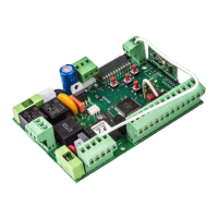
M
UP/ BROWN
DOWN / BLACK
COMMON / BLUE
GND / GREEN-YELLOW
Radio
module
Buzzer
Relay 7A
Learning
button
2. Configuration
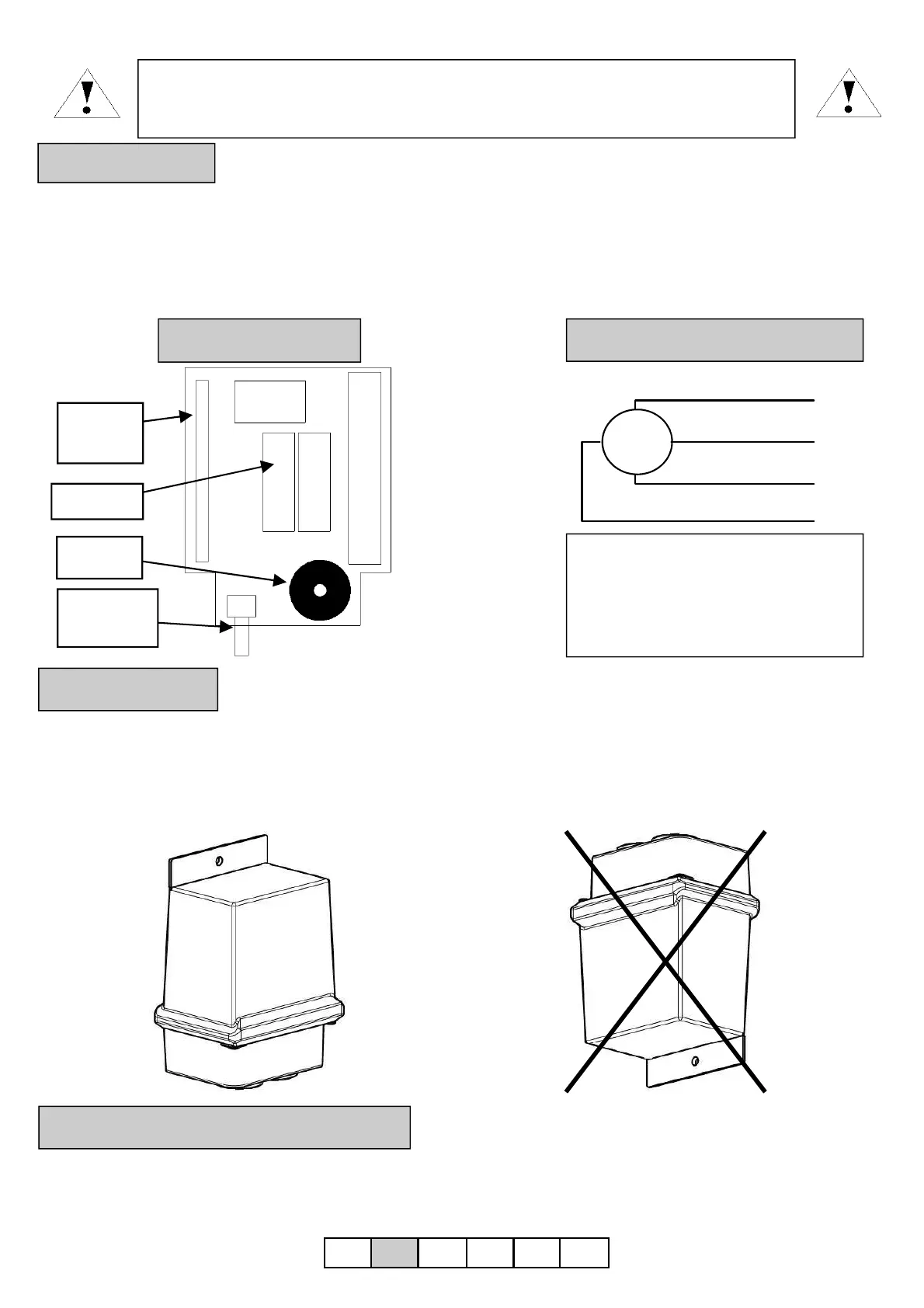
4. Installation
5. Modality of relay’s activation
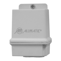
For an external installation, is indispensable to respect the orientation of the control unit. The correct
installation is with the power supply cables and the motor’s cables getting out from the down as reported on
the box.
Correct installation
UNCORRECT installation
 Loading...