Sectio
3
Unpack and Prepare for
Operation
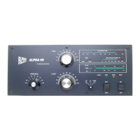
(Refer to Figures. 1-5, pages 13, 19, 21)
Carefully unpack amplifier and transformer.
Inspect both for physical damage. Save all packing material for future use.
AC Primary Connections & Amplifier Grounding.
Remove the amplifier top cover. Primary voltage taps are selected at the terminal strip
numbered “1” to “7” and located on the mains board mounted on the chassis center
divider, left of the transformer. Connect the two wires labeled “A” and “B” for the line
voltage to be used, as shown in the following table. The two short jumper wires
supplied are not used on 190-250V, but must be connected as shown for operation on
90-130V mains.
Install the transformer.
Only one possible transformer orientation allows mating all its connectors without
straining leads.
Warning! The transformer is very heavy and must be moved with due
caution using only the lifting handle.
Lift the transformer high enough to clear the right side chassis lip and move it sideways
into the chassis. USE CAUTION! PROCEED SLOWLY to avoid damaging wires
or components. From underneath, insert the supplied bolts with washers through the
clearance holes in the chassis and into the nuts in the transformer base. CAUTION!
Mate transformer connectors carefully and gently to insure that all connector pins
engage correctly and fully.
While the top cover is removed, make sure each tube are firmly seated in its socket,
rubber exhaust chimneys is fully and correctly installed, and anode connector is tightly
clamped to each tube. The silicone rubber chimneys installed on the 4CX800 tubes are
Manual Alpha 99 Rev 1.doc
17