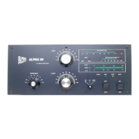
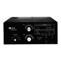
Radio Alpha Products Inc. ® Alpha 99
18
an absolutely essential part of the cooling system. Make sure the chimneys are straight
and fully installed so that the bottom of the chimney is firmly against the tube deck and
completely covers the airflow openings in the deck. Tube cooling air must exit only
through the tube anode fins; it must not be allowed to escape outside them. Failure to
ensure proper cooling airflow may result in tube damage or destruction which is not
covered under warranty.
AC Primary Connections & Amplifier Grounding
Primary voltage taps are selected at the terminal strip numbered “1” to “7” and located
on the mains board mounted on the chassis center divider, left of the transformer.
Connect the two wires labeled “A” and “B” for the line voltage to be used, as shown in
the following table. The two short jumper wires supplied are not used on 190-250V,
but must be connected as shown for operation on 90-130V mains.
PRIMARY “A” Terminal “B” Terminal Blower* Jumpers
230-250V 4 ** 2** 4 & 2** Not used for
190 -
250Voperation
210-230V 4 3 4 & 3 Not used for
190 -
250Voperation
190-210V 5 3 4 & 3 Not used for
190 -
250Voperation
110-130V 4 6 4 & 7 1 - 2, 6 - 7
90-110V 5 6 4 & 7 1 - 3, 6 – 7
* The blower wires are the 2 black wires marked “4” and “X”, ( 4 to terminal 4, X to 2,
3, or 7 per table). Optional external muffin fan has 2 black wires, one is connected
with blower wire 4 and the other to the same terminal as blower wire X (2, 3, or 7 per
table)
** Factory settings.
NOTE: If you intend to operate the amplifier on any of the 90 - 130V
settings, the two lower fuses on the rear panel (2 amp) will have to be
changed to 5 amp to allow for the increased in-rush current.