2
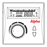
3. Installation of Transmitter - see Figs. 3 and 4
Note: A clearance of 80 mm is required above the transmitter to allow the front cover to be
raised as shown in Fig. 4.4.
Locate and fit the Transmitter as in Fig. 4, taking into consideration where not to position the
Transmitter as shown in Fig. 3. Steel reinforced walls, large metallic objects e.g. kitchen
appliances, filing cabinets, mirrors etc. can reduce, deflect or block radio signals between
the Transmitter and Receiver.
The maximum allowable distance between Receiver and Transmitter is:-
i. In open air 50 m.
ii. In building 20 m to 30 m depending on radio wave obstruction.
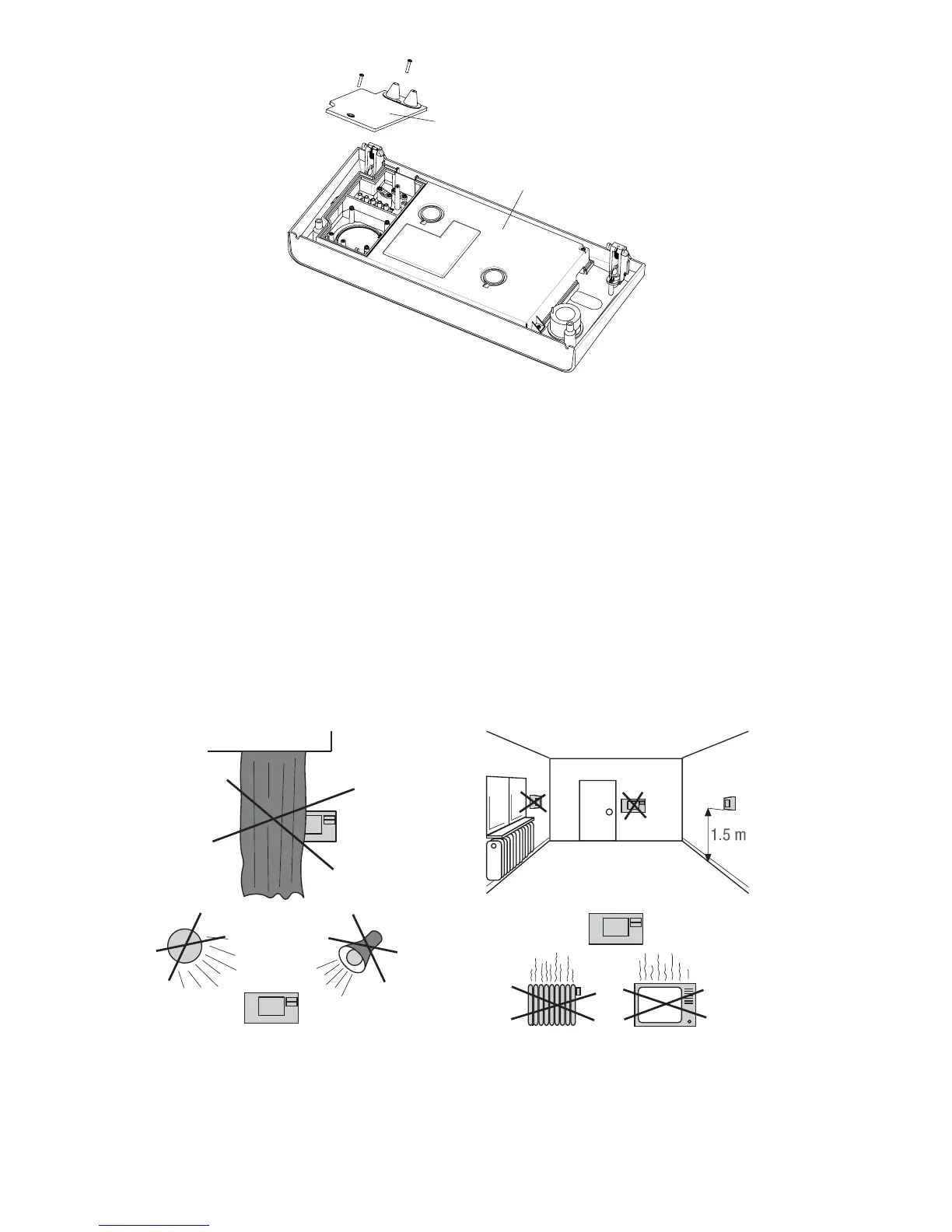
Clock cover
Rear of control panel
Fig. 2
Fig. 3