29
Alpha InTec² 26E, 30CE and 35CE - Commissioning
5.9 FINAL ASSEMBLY
1. Raise the control panel and secure in position with the screws provided.
2. Clip the bottom cover plate in position as shown in Fig. 4.4.
3. If the boiler is to be left in service with the User, set the controls, clock (if fitted, see User's Operating manual) and room
thermostat (if fitted) to the User's requirements.
4. If the boiler is not to be handed over immediately, close the boiler gas service cock and switch off the electrical supply.
5. If there is any possibility of the boiler being left during frost conditions, then the boiler and system should be drained
(refer to Section 7.2). It is recommended that a label is attached to the boiler drawing attention to the fact that the
system has been drained.
6. Complete the details of the installation in the Benchmark Checklist at the back of these instructions.
5.10 USER INFORMATION
The User must be advised (and demonstrated if necessary) of the following important points:-
1. How to light and turn off the boiler and how to operate the system controls.
2. The importance of annual servicing of the boiler to ensure safe and efficient operation and maintain the boiler guarantee.
3. That any servicing or replacement of parts must only be carried out by a Gas Safe registered engineer.
4. Ensure that the boiler controls and room thermostat (if fitted) are set to the User's requirements.
5. Tell the User about the sealed system pressure.
6. Tell the User that if the electrical supply is on and the boiler has not operated for 24 hours for heating or hot water, the
pump will automatically operate for 30 seconds.
7. Explain to the User that an internal frost thermostat is fitted in the boiler, and that the electrical supply to the boiler must
be left on for the thermostat to operate, i.e. the boiler must be set to standby.
8. Explain to the User that in certain weather conditions the flue terminal will emit a plume of steam, i.e. water vapour. This
is safe and quite normal.
9. Show the User the position of the condensate discharge pipes.
10. Leave the instructions with the User.
11. Ensure the Benchmark Checklist at the back of these instructions has been completed after the boiler has been
installed and commissioned.
Note: It is a requirement that the installation is registered by the installer through the Gas Safe Gas Work Notification
Scheme.
12. Leave these Installation and Servicing instructions with the User for use on future calls.
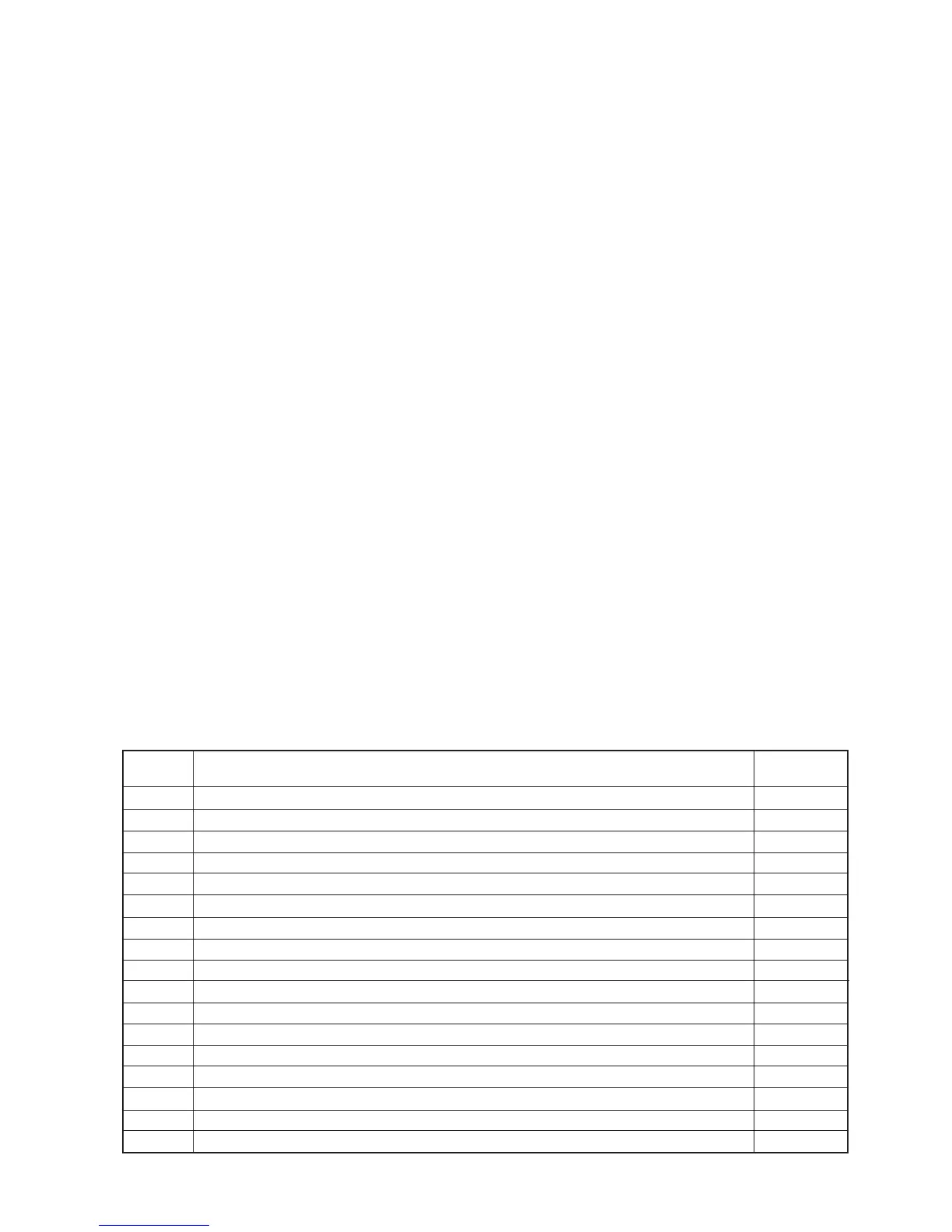
5.11 INFORMATION MENU
By pressing the info button (item 4 in Fig. 5.1) the information menu is accessed, this will then show the information
according to the table below.
Info Menu
(d - prefix)
d0
d1
d2
d3
d4
d5
d6
d7
d8
d9
d10
d11
d12
d13
d14
d15
d16
Information
Optional cylinder temperature adjustment
Flame signal
Central heating flow temerature
Domestic hot water temperature leaving the boiler
Central heating set point temperature
Domestic hot water set point temperature
External weather compensation probe temperature (value flashes if negative)
Mains inlet temperature or FlowSmart cylinder temperature (if sensor fitted)
Central heating return temperature
Fault history - by rotating the CH knob (item 6 in Fig. 5.1) in this menu the last five faults will be displayed
Fault history reset - when in this menu, pressing the reset button will clear the fault code history
Overheat sensor reading
Pump speed (0 = OFF, 1,2,3,4,5,6,7,8,9)
Domestic hot water flow rate
Pump flow rate
Fan speed during current operation
Flue sensor reading
Units
Shown
°C
kOhm/10
°C
°C
°C
°C
°C
°C
°C
Error code
°C
Speed level
l/min
l/h/100
rpm/100
°C