32
Alpha InTec² 26E, 30CE and 35CE - Commissioning
Note: These must be set to the correct values relating to the boiler installed. When changed 'E62' will be displayed and full
calibration is required. See Section 5.13.
Parameter Feature Description Range
0 - 99 %
0 - P2
0 - 99 %
0 - 7
0 - 7
0 - 9
0 - 1
-9 +9 °C
-9 +9
The maximum output of the boiler during DHW production as a
percentage of the maximum available output
The minimum heat output of the boiler during DHW and CH
production as a percentage of the available heat output
The maximum output of the boiler during CH production as a
percentage of the maximum available output
Boiler functions/configurations when optional relay PCB is fitted
0 = Off
1 = Main zone control (with Climatic controller)
2 = General alarm
3 = CH phase active (external pump)
4 = External gas valve power supply
5 = Flow Smart enabled
6 = Diverter valve enabled
7 = When boiler pump active
Boiler functions/configurations when optional relay PCB is fitted
0 = Off
1 = General alarm
2 = CH phase active (external pump)
3 = External gas valve power supply
4 = Secondary zone control (volt free switching across
57 & 58 on relay PCB contacts)
5 = Heat pump function with dedicated controls
6 = Alpha Trace heating cable enabled
7 = When boiler pump active
Boiler functions/configurations when optional relay PCB is fitted
0 = Off
1 = Chiller remote activation (with Climatic controller)
2 = General alarm
3 = CH phase active (external pump)
4 = External gas valve power supply
5 = Heat pump function with dedicated controls
6 = Activation of storage tank pump (with Climatic controller)
7 = Main zone control (with Climatic controller)
8 = Alpha Trace heating cable enabled
9 = When boiler pump active
The pump can function in two ways.
0 Intermittent - In Winter mode the pump is managed by the
room thermostat or by the remote control
1 Continuous - In Winter mode the pump is always on
If the reading of the external sensor is incorrect it is possible to
offset the reading.
(Over the value of +9 the display shows 'CE', for external control
connection only used with system supervisor connection)
If required, it is possible to increase or decrease the hot water
output and adjust the DHW flow in Automatic mode.
Positive values increase the flow. Negative values decrease the
flow
DHW max.
Min. output
DHW and CH
Heating max.
Relay 1
(optional)
Relay 2
(optional)
Relay 3
(optional)
Pump functioning
External sensor
correction
DHW adjusted flow
rate correction
P0
P1
P2
P3
P4
P5
P6
P7
P8
Default
99 %
0 %
1
6
0
0
0
0
26CE - 75 %
26CE (LPG) - 71 %
30CE - 86 %
30CE (LPG) - 82 %
35CE - 83 %
35CE (LPG) - 79 %
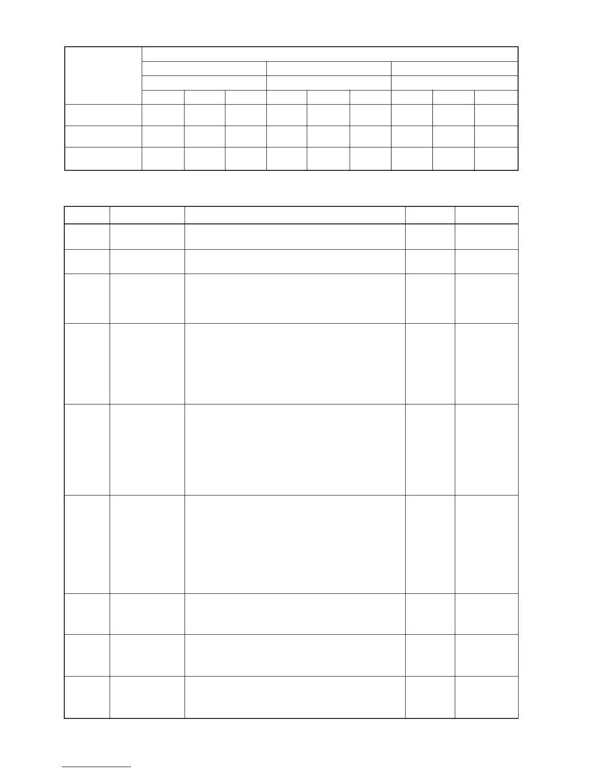
Fan Speed set values according to boiler model and 'F' parameter (flue setting)
Parameter G
Sub-menu s
InTec
2
26CE
F parameter setting
InTec
2
30CE
F parameter setting
F0 = 0
13
(1300 rpm)
57
(5700 rpm)
37
(3700 rpm)
F0 = 1
13
(1325 rpm)
59
(5950 rpm)
37
(3700 rpm)
F0 = 2
13
(1375 rpm)
62
(6200 rpm)
37
(3700 rpm)
F0 = 0
12
(1250 rpm)
61
(6100 rpm)
37
(3700 rpm)
F0 = 1
12
(1275 rpm)
63
(6350 rpm)
37
(3700 rpm)
F0 = 2
13
(1300 rpm)
64
(6400 rpm)
37
(3700 rpm)
S2 (ign. fan speed)
S1 (max. fan speed)
S0 (min. fan speed)
InTec
2
35CE
F parameter setting
F0 = 0
13
(1300 rpm)
64
(6400 rpm)
36
(3600 rpm)
F0 = 1
13
(1300 rpm)
66
(6600 rpm)
36
(3600 rpm)
F0 = 2
13
(1300 rpm)
68
(6800 rpm)
36
(3600 rpm)