72-EN
01GB07IVA310R.fm
ALPINE IVA-D310R 68-02278Z24-A (EN)
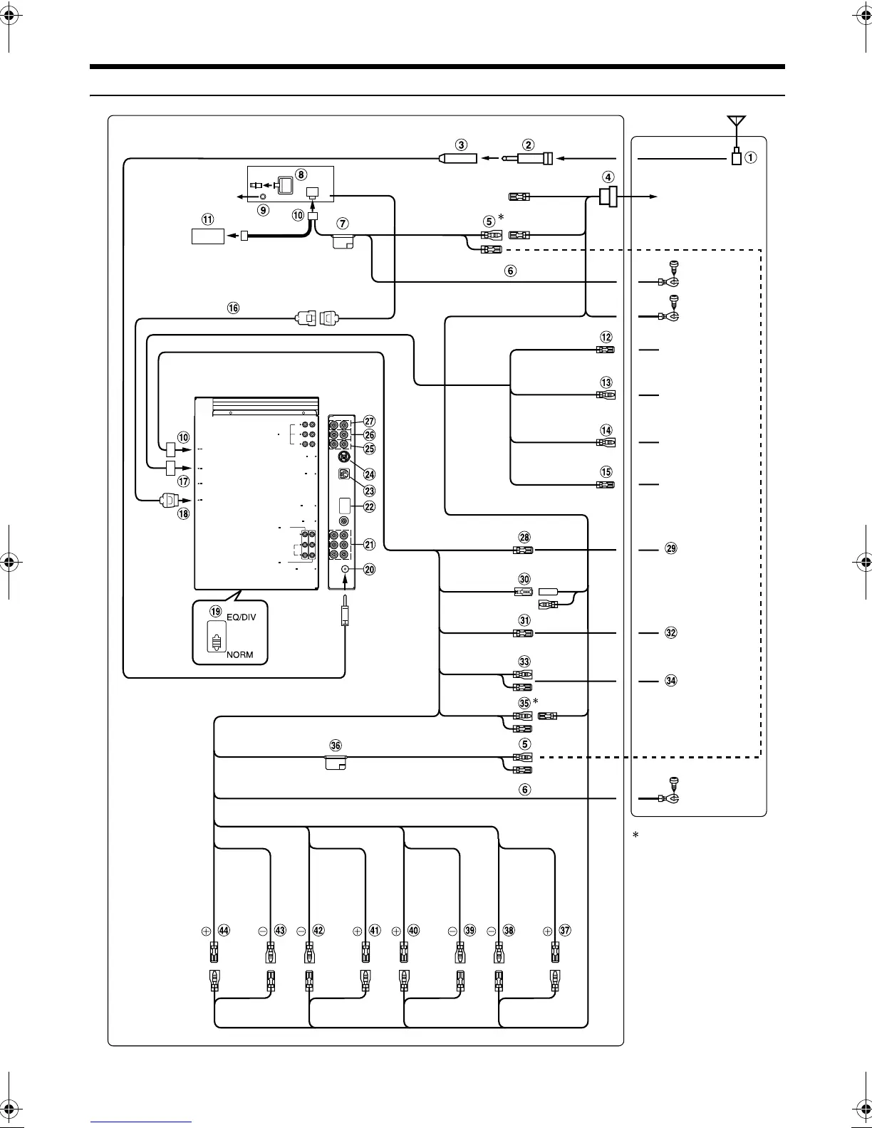
Connections (IVA-D310R/IVA-D310RB Wiring Diagram)
• Set the system switch to “NORM” when only a changer is connected (when the Ai-NET compatible equalizer is not used).
DISPLAY OUT
NAVIGATION IN
REMOTE IN/ OUT
PRE IN/OUT
Ai-NET
FRONT
L
R
SUBW.
REAR
POWER SUPPLY
AUX OUT
AUX IN
VIDEO
AUDIO
R
L
RADIO ANTENNA IN
CAMERA IN
AV SELECTOR
EXT.OUT
IVA-D310R/IVA-D310RB
<Monitor>
To plus side of
the back lamp
signal lead of the
car
To remote input
lead.
To remote output
lead.
To remote control
interface box
(Yellow)
(Yellow)
(Black)
IVA-D310R/IVA-D310RB
Tune r BOX
(Black)
(White/Brown)
(White/Brown)
(Orange/White)
(White/Pink)
(Blue/White)
(Blue)
(Pink/Black)
(Yellow/Blue)
(Yellow)
(Black)
(Red)
(Red)
(Blue)
SPEAKER
LEFT
FRONT
(White/
Black)
SPEAKER
LEFT
REAR
(Green)
SPEAKER
RIGHT
REAR
(Violet/
Black)
SPEAKER
RIGHT
FRONT
(Grey)
To monitor
control lead.
Note:
Be sure to connect the leads
correctly after identifying the
ISO connector terminals for
the Battery and lgnition
(ACC).
F-Lch R-Lch
R-Rch
F-Rch
BATTERY
BATTERY
GND
GND
REMOTE OUT
REMOTE IN
REVERSE
M.CONT
REMOTE
TURN-ON
POWER ANT
AUDIO
INTERRUPT IN
PARKING
BRAKE
BATTERY
GND
ACC
ACC
P.ANT
Antenna
To the instrument
cluster illumination
lead
(White) (Green/
Black)
(Violet)
(Grey/
Black)
ILLM
(Orange)
Not used
01GB00IVAD310R.book Page 72 Thursday, January 13, 2005 10:40 AM