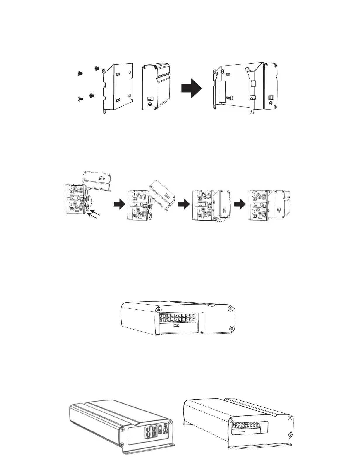
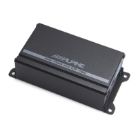
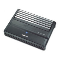
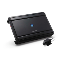
2. HU bracket connected to HU
a. Remove the 2 bottom corner screws from HU and place to the side. These are not used.
i. Use the 8mm screws in the kit. These replace the short screws removed from the HU
and placed to the side.
b. The attachment process is to insert the assembled amp and its bracket with two tabs
intotheir slot on the upper portion of radio rear panel. Pivot down. See below image:
Mount point A
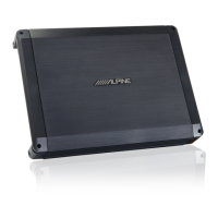
3. Universal bracket to amp.
a. Each end gets a unique bracket.
b. Remove 3 Philips screws from end panels, do not lose these.
c. Move antenna cable to the cut out space and then nish pivoting the amp to make
contact.
d. Replace the 2 screws. Do not use an electric screw gun, you will strip it. See above
image: Mount point B.
c. Place each bracket so that the 3 holes are visible and aligned.
i. For the switch control side the silk screen will be completely visible.
ii. Re use the 3 screws and replace. This will x the bracket in place.
iii. Tighten to snug plus 1/8 turn to be tight.
iv. Repeat for opposite side.
d. Completed side:
Assembly of;
1. HU bracket to amp.
a. Attach bracket to amp; use the 4 black button head screws included. Tighten with 3mm
hex tool.
b. Place button head screws in place and tighten to be snug.
c. Secure the screw by tightening just about ¼ turn more.
d. Follow diagram below.
3 screws on
each side
i. Mount point A
Remove 2 bottom
corner screws
from HU
ii. Mount point B