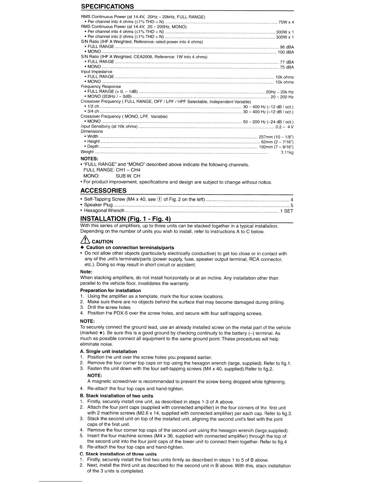
SPECIFICATIONS
..........
77
dBA
..
....... 75 dBA
. 10k ohms
. 10k ohms
...... 300W
x 1
...300W
x 1
..
75W x 4
..
20Hz - 20k
Hz
..
...... 20 - 200 Hz
..
..
50 - 200 Hz
(-24
dB I oct.)
.........................
0.2-
4V
.................................. 257mm (10
-1/8")
...................................................... 62mm
(2
-7/16")
192mm
(7
- 9/16")
3.11kg
RMS Continuous Power (at 14.4V, 20Hz - 20kHz, FULL RANGE)
• Per channel into 4 ohms
(,;;1
% THD +
N)
....
RMS Continuous Power (at 14.4V, 20 - 200Hz, MONO)
• Per channel into 4 ohms
(,;;1%
THD +
N)
..
• Per channel into 2 ohms
(,;;1%
THD + N)
..
SIN
Ratio (IHF A Weighted, Reference: rated power into 4 ohms)
• FULL RANGE
..
. 96 dBA
• MONO
..
100 dBA
SIN
Ratio (IHF A Weighted, CEA2006, Reference: 1W into 4 ohms)
• FULL RANGE.
..
.
• MONO
.. ..
Input Impedance
• FULL RANGE.
• MONO ....
Frequency Response
• FULL RANGE (+
0,
- 1dB) .....
• MONO (200Hz
1-
3dB) .
Crossover Frequency ( FULL RANGE, OFF
I LPF I HPF Selectable, Independent Variable)
·112
ch
..
30 - 400 Hz
(-12
dB I oct.)
·314
ch
..
30 - 400 Hz
(-12
dB I oct.)
Crossover Frequency ( MONO,
LPF,
Variable)
• MONO
..
..
input Sensitivity (at 10k ohms)
..
Dimensions
• Width
• Height
• Depth
Weight ......
NOTES:
• "FULL RANGE" and "MONO" described above indicate the following channels.
FULL
RANGE:
CH1
- CH4
MONO: SUB
W.
CH
• For product improvement, specifications and design are subject to change without notice.
ACCESSORIES
• Self-Tapping Screw (M4 x 40, see
CD
of Fig. 2 on the left) 4
• Speaker Plug....
..
5
• Hexagonal Wrench 1 SET
INSTALLATION (Fig. 1 - Fig. 4)
With this series of amplifiers, up to three units can be stacked together
in
a typical installation.
Depending on the
number
of units you wish to install, refer to instructions A to C below.
'&CAUTION
• Caution
on
connection
terminals/parts
• Do not allow other objects (particularly electrically conductive) to get too close
or
in contact with
any of the unit's terminals/parts (power supply, fuse, speaker output terminal, RCA connector,
etc.). Doing so may result in short circuit
or
accident.
Note:
When stacking amplifiers,
do
not install horizontally
or
at an incline. Any installation other than
parallel to the vehicle floor, invalidates the warranty.
Preparation
for
installation
1.
Using the amplifier as a template, mark the four screw locations.
2.
Make sure there are no objects behind the surface that may become damaged during drilling.
3.
Drill the screw holes.
4.
Position the PDX-5 over the screw holes, and secure with four self-tapping screws.
NOTE:
To
securely connect the ground lead, use an already installed screw on the metal part of the vehicle
(marked
*).
Be sure this is a good ground by checking continuity to the battery
(-)
terminal. As
much as possible connect all equipment to the same ground point. These procedures will help
eliminate noise.
A.
Single
unit
installation
1.
Position the unit over the screw holes you prepared earlier.
2.
Remove the four corner top caps
on
top using the hexagon wrench (large, supplied). Refer to fig.1.
3.
Fasten the unit down with the four self-tapping screws (M4 x 40, supplied).Refer to fig.2.
NOTE:
A magnetic screwdriver is recommended to prevent the screw being dropped while tightening.
4.
Re-attach the four top caps and hand-tighten.
B. Stack
installation
of
two
units
1.
Firstly, securely install one unit, as described
in
steps 1-3 of A above.
2.
Attach the four joint caps (supplied with connected amplifier) in the four corners of the first unit
with 2 machine screws (M2.6 x 14, supplied with connected amplifier) per each cap. Refer to fig.3.
3.
Stack the second unit on top of the installed unit, aligning the second unit's feet with the joint
caps of the first unit.
4.
Remove the four corner top caps of the second unit using the hexagon wrench (Iarge,supplied).
5.
Insert the four machine screws (M4 x 36, supplied with connected amplifier) through the top of
the second unit into the four joint caps of the lower unit to connect them together. Refer to fig.4
6.
Re-attach the four top caps and hand-tighten.
C.
Stack
installation
of
three
units
1.
Firstly, securely install the first two units firmly as described in steps 1 to 5 of B above.
2.
Next, install the third unit as described for the second unit
in
B above. With this, stack installation
of the 3 units is completed.

 Loading...