EasyManua.ls Logo

Alpine PDR-M65 - User Manual

Alpine PDR-M65
19 pages
Print Icon
To Next Page IconTo Next Page
Loading...
FOR CAR USE
ONLY
/POUR
APPLICATION AUTOMOBILE/PARA USO
EN AUTOMQVILES
PDR-M65
MONO
POWER
AMPLIFIER
PDR-FSO
4 CHANNEL POWER
AMPLIFIER
OWNER'S MANUAL
Please
read before using this equipment.
MODE
D'EMPLOI
Veuillez lire avant d'utiliser cet appareil.
MANUAL
DE
OPERACION
Lealo
antes de
utilizar
este equipo.
ALPINE
ELECTRONICS
OF
U.K.
LTD.
Alpine House
ALPINE
ELECTRONICS
MARKETING, INC.
1-7, Yukigaya-Otsukamachi,
Ota-ku,
Tokyo
145-0067,
JAPAN
Fletchamstead
Highway,
Coventry CV4
9TW,
U.K.
Phone:
03-5499-4531
ALPINE
ELECTRONICS
OF
AMERICA, INC.
19145 Gramercy
Place,
Torrance,
California 90501,
U.S.A.
Phone 1-800-ALPINE-1
(1-800-257-4631)
ALPINE
ELECTRONICS
OF
AUSTRALIA
PTY.
LTD.
161-165
Princes
Highway, Hallam
Victoria
3803, Australia
Phone 03-8787-1200
ALPINE
ELECTRONICS
GmbH
Wilhelm-Wagenfeld-Str.
1-3,
80807
Munchen,
Germany
Phone 089-32
42
640
JElL
Moon
Hwa
Co.
18-6, 3Ga, Pil_dong,
Jung_gu,
Seoul, Korea
Phone 0870-33
33
763
ALPINE
ELECTRONICS
FRANCE
S.A.R.L.
(RCS
PONTOISE
B 338
101
280)
98,
Rue
de
Ia
Belle Etoile, Z.l. Paris
Nord
II,
B.P.
50016, 95945 Roissy
Charles
de
Gaulle
Cedex,
France
Phone 01-48638989
ALPINE
ITALIA
S.p.A.
Vi
ale
C.
Colombo
8,
20090
Trezza
no
Sui
Naviglio (MI), Italy
Phone 02-484781
ALPINE
ELECTRONICS
DE
ESPANA,
S.A.
Portal
de Gamarra 36, Pabell6n,
32
01013
Vito ria
(Aiava)-APDO
133, Spain
Phone
945-283588
Designed
by
ALPINE
Japan
Printed
in Korea
68-25285ZSS-A
(Y
_AS)
M35145230 1
0
I
I
I
Question and Answer IconNeed help?

Do you have a question about the Alpine PDR-M65 and is the answer not in the manual?

Summary

WARNING

SERVICE CARE

ACCESSORIES

INSTALLATION

ATTACHING THE TOP COVER AND LOGO PLATE

CONNECTIONS

Speaker Output Terminals

Explains speaker output terminals and polarity.

RCA Input Jacks

Connects head unit line out to amplifier via RCA cables.

Pre-Out Jacks (PDR-M65 only)

Provides a full-range line level output for driving a second subwoofer amp.

Fuse

Specifies fuse ratings for PDR-M65 and PDR-F50.

Power Supply Terminal

Terminal for connecting the power supply.

Remote Bass Control (PDR-M65 only)

Connects to an optional unit for remote bass level adjustment.

Battery Lead

Connects battery lead with in-line fuse to positive terminal.

Ground Lead

Connects ground lead securely to a clean metal spot on the chassis.

Remote Turn-On Lead

Connects to the head unit's remote turn-on lead.

Cautions on Wire Lead Connections

Required Wire Size

Lists wire gauge requirements for battery, remote, and speaker leads.

CONNECTION CHECK LIST

SWITCH SETTINGS

Subsonic Filter (PDR-M65 only)

Cuts ultra-low frequencies to protect speakers or minimize wasted power.

Crossover Frequency Adjustment Knob

Adjusts crossover frequency between 50 to 400 Hz.

Bass EQ Adjustment Knob (PDR-M65 only)

Adds up to +12 dB bass boost at 50 Hz.

Input Gain Adjustment Control

Procedure to set amplifier's input gain for optimal sound.

Crossover Mode Selector Switch (PDR-F50 only)

Selects OFF, HP, or LP filter mode for speakers.

Bass EQ Selector Switch (CH-3;4) (PDR-F50 only)

Selects Bass EQ boost levels (+6 dB or +12 dB) for subwoofers.

Input Channel Selector Switch (PDR-F50 only)

Selects 2-channel or 4-channel input mode.

About Power Indicator

SYSTEM DIAGRAMS

1 Subwoofer System

Shows typical connection for a single subwoofer.

2 Subwoofer System (MONO)

Shows typical connection for a mono subwoofer setup.

PDR-F50 TYPICAL SYSTEM CONNECTIONS

4 Speaker System (4-Channel Input)

Shows typical connection for 4 speakers with 4-channel input.

4 Speaker System (2-Channel Input)

Shows typical connection for 4 speakers with 2-channel input.

BRIDGED CONNECTIONS

2 Speaker + Subwoofer System

Shows typical connection for 2 speakers and a subwoofer in bridged mode.

SPECIFICATIONS

LIMITED WARRANTY

Products Covered

Details which car audio products and accessories are covered by the warranty.

Length of Warranty

Specifies the warranty period as one year from the first consumer purchase.

Who is Covered

States only the original purchaser residing in the US, PR, or Canada is covered.

What is Covered

Covers defects in materials and workmanship (parts and labor).

What is Not Covered

Lists exclusions like shipping damage, accident, misuse, or acts of God.

How to Obtain Warranty Service

Outlines the process for getting warranty service, including shipping and proof of purchase.

How We Limit Implied Warranties

Limits implied warranties to the duration of the express warranty.

How We Exclude Certain Damages

Disclaims liability for incidental and consequential damages.

How State;Provincial Law Relates to the Warranty

Explains how local laws may affect warranty rights.

In Canada Only

States warranty validity requires installation by an authorized center in Canada.

How to Contact Customer Service

Provides contact numbers for customer service and the website.

Overview

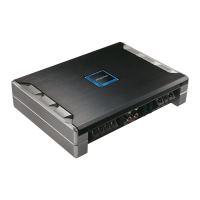
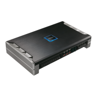
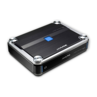
The Alpine PDR-M65 Mono Power Amplifier and PDR-F50 4 Channel Power Amplifier are designed for mobile 12V applications, providing high-quality audio output for car audio systems. These amplifiers are engineered to deliver robust sound performance while incorporating features for safe and effective operation.

Function Description

The PDR-M65 is a mono power amplifier, ideal for driving subwoofers, while the PDR-F50 is a 4-channel power amplifier suitable for full-range speakers, tweeters, or mid-range systems, and can also be bridged for subwoofer applications. Both units are designed to amplify audio signals from a head unit, delivering increased power to speakers.

Key controls and features include:

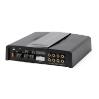
  • Speaker Output Terminals: These terminals are designed for connecting speakers. For the PDR-M65, the output is monaural, and reversing subwoofer polarity may be beneficial for optimal bass. For the PDR-F50, bridged connections are possible, where the left positive connects to the speaker's positive terminal and the right negative to the speaker's negative terminal. It is crucial to observe correct polarity and avoid connecting speaker (-) terminals to the vehicle's chassis.
  • RCA Input Jacks: These jacks allow connection to the line-out leads of a head unit using RCA extension cables. Proper channel connections (Left to Left, Right to Right) must be observed.
  • Pre-Out Jacks (PDR-M65 only): The PDR-M65 includes line-level pre-out jacks, providing a full-range output unaffected by the crossover, making it suitable for driving a second subwoofer amplifier.
  • Power Supply Terminal: This terminal is for connecting the battery lead, ground lead, and remote turn-on lead.
  • Remote Bass Control (PDR-M65 only): An optional Remote Bass Control Unit can be connected to adjust the output level remotely, complementing the gain level setting between the amplifier and head unit.
  • Subsonic Filter (PDR-M65 only): This filter cuts ultra-low frequencies from the input signal before amplification. It is useful for protecting smaller speakers, minimizing wasted power from inaudible sound, and preventing over-excursion of subwoofers in vented enclosures below their tuning frequency.
  • Crossover Frequency Adjustment Knob (PDR-M65: LP FILTER): This knob allows adjustment of the crossover frequency between 50 to 400 Hz for the PDR-M65.
  • Bass EQ Adjustment Knob (PDR-M65 only): This knob provides a 50 Hz bass boost up to +12 dB to fine-tune bass response.
  • Input Gain Adjustment Control: This control sets the amplifier's input gain. It should be adjusted by first increasing the head unit volume until distortion, then reducing it slightly, and finally increasing the amplifier gain until distortion, then reducing it slightly to achieve the optimum setting.
  • Crossover Mode Selector Switch (PDR-F50 only): This switch offers three modes:
    • OFF: For full-range speakers or when using an external electronic crossover, providing full frequency bandwidth.
    • HP (High Pass): For tweeter/midrange systems, attenuating frequencies below the crossover point at 12 dB/octave.
    • LP (Low Pass): For subwoofers, attenuating frequencies above the crossover point at 12 dB/octave.
  • Bass EQ Selector Switch (CH-3/4) (PDR-F50 only): This switch sets a 50 Hz bass boost to "+6 dB" or "+12 dB" for subwoofer applications.
  • Input Channel Selector Switch (PDR-F50 only): This switch selects between 2-channel or 4-channel input modes. In "1/2" mode, the signal from CH-1/2 is copied to CH-3/4, eliminating the need for Y-adapters. In "3/4" mode, both CH-1/2 and CH-3/4 inputs are independent, requiring a 4-channel source.
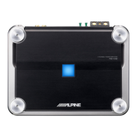
  • Power Indicator: A blue light indicates normal amplifier circuit operation. A blinking red light signifies high operating temperature, while a solid red light indicates an abnormal amplifier circuit, electrical short, or high supply current.

Usage Features

  • Installation: The amplifiers generate considerable heat, so they should be mounted in a location with free air circulation, such as inside the trunk. Installation involves removing the top cover, marking screw locations using the amplifier as a template, drilling holes, and securing the unit with self-tapping screws.
  • Wiring: Proper wiring is critical for safety and performance.
    • Battery Lead: An in-line fuse with the correct ampere rating (70 amp for PDR-M65, 60 amp for PDR-F50) must be added as close as possible to the battery's positive (+) terminal. The minimum required wire gauge is 4 AWG/21 mm².
    • Ground Lead: Connect securely to a clean, bare metal spot on the vehicle's chassis. All audio components should be grounded to the same point to prevent ground loops. The minimum required wire gauge is 4 AWG/21 mm².
    • Remote Turn-On Lead: Connect to the remote turn-on (positive trigger, (+) 12V only) lead of the head unit. If a remote turn-on lead is unavailable, or if the head unit's power antenna lead has limitations, the amplifier's turn-on lead must be connected to a switched power source (ignition) with a 3A fuse. An optional SPST switch can be installed for manual control.
    • Speaker Output Leads: The recommended wire gauge is 8 AWG (8 mm²) for PDR-M65 and 12 AWG (3 mm²) for PDR-F50.
    • Wire Lead Connections: Insulation should be removed from wire ends by 7-10 mm. Set screws should be tightened with the provided hexagon wrench. Insulated shrink tubing should be used to cover any exposed wire.
  • Noise Prevention: To prevent external noise, route leads at least 10 cm (4") away from the vehicle's harness and keep battery power leads separate from other leads.
  • Bridged Connections (PDR-F50): When bridging, ensure proper connections to avoid low output. A Y-adapter is not required if a stereo/mono pair line output is used to drive both inputs of the bridged amp.

Maintenance Features

  • Fuse Replacement: Use the correct ampere rating (35A x 2 for PDR-M65, 30A x 2 for PDR-F50) when replacing fuses to prevent fire or electric shock.
  • Troubleshooting Power Indicator:
    • Blinking Red (High Operating Temperature): Decrease the vehicle's interior temperature. The indicator should change to blue.
    • Solid Red (Abnormal Circuit/Short/High Current): Turn off the power supply, eliminate the cause, then restart. If it remains red, consult a dealer.
    • Solid Red (High Power Supply Voltage): Use the correct power supply voltage. The indicator should change to blue.
  • Switch Settings: Before adjusting any selector switch, turn off the power and use a small screwdriver to change the setting.
  • General Care: Avoid installing the unit in locations with high moisture or dust, as this can lead to product failure. Do not block vents or radiator panels to prevent heat buildup. Do not disassemble or alter the unit, as this may cause accidents, fire, or electric shock. If a problem occurs, halt use immediately and return the unit to an authorized Alpine dealer for repair.
  • Warranty Service: For warranty service, provide a detailed problem description, proof of purchase, and securely package the product for shipment to an authorized Alpine Service Center or Alpine.

Alpine PDR-M65 Specifications

General IconGeneral
Power Output (RMS)65W x 4 (4Ω)
Power Output (Peak)130 watts x 4
RMS Power Output65 watts x 4
Bridged Power Output130W x 2 (4Ω)
CEA-2006 Power Output65W x 4 @ 4 Ohms
Frequency Response10 Hz - 30 kHz
Input Sensitivity0.2V - 4V

Related product manuals