1. Check the wire gauge
Notes;
The available
speaker
wire gauge for this unit is AWG8-
AWG16
o
If
in doubt, consult
your
dealer
regarding correct wire
gauge to
use
2. Strip back
between
7·10mm
(9/32
0
-318
0
)
of
the wire's
insulation to expose
the
conductor.
Notes;
Ifthe length of the exposed conductor is too shore a poor
connection may
occur
causing operation tailure or sound
interruption.
Conversely,
il
the
exposed
conductor
is
too
long, an
electrical short-circuit
may
occur
3. Loosen fully the
speaker
plug's 2 hexagon screws using
the
hexagon
wrench
(small, supplied).
4. Insert fully the exposed conductor of the
speaker
wire
into
the
wire
terminal hole. Refer
to
Fig.8
Note;
Insertlhe
speaker wire observing the
+/-
indications on
the speaker plug. Insert the positive
speaker
wire into
the positive speaker terminal. and the negative speaker
wire into the negative
speaker
terminaL
5. Tighten the 2 hexagon screws using the hexagon wrench
(small, supplied).
$.~
Power
Indicator
Lights
up
when power is on
Is
off
when power is off
When
you connect the speaker wire to the unit, you need to inser.
the speaker wire into the speaker plug. Below explains
how
to
insert the speaker wire into the speaker plug
o
Input
Gain
Adjustment
Control
(SUB
W.)
Set the
PDX·5
input gain to the minimum position. Using a dy-
namic
CD
as a source. increase the
head
unit volume until the
output distorts. Then. reduce Ihe volume t
step
(or until the out-
put is no longer distorted). Now. increase the amplifier gain unlil
the sound from the speakers becomes distorted. Reduce the gain
slightly so the sound is
no
longer
distorted to achieve the
opU-
mum gain selling
Note;
Use the supplied hexagon screws forthis connection.
It
is highly
recommended that this
be
carried out
by
the
dealer
II you make this connection yourself. ensure the connection is
correct
by
fOllowing the instructions below carefully.
Be
sure
to
use
the
supplied
hexagon
screws
for
this
connection
For safety reasons, connect the battery wire last
To
prevent disconnection of the leads
or
dropping of the unit.
do
nol
carry the unit
by
the wire
Be
sure
to
add a fuse as close as possible to the ballery.
Make sure
to
use a fuse of the correct rating for the power
wire
6'
Crossover
Frequency
Adjustment
Knob
(LP
FILTER)
Permits the adiustment
of
the
crossover frequency. Rotate the
knob to select anyfrequency between
50
and 200 Hz as the cross-
over point.
•
Cautions
on
speaker
wire
connections
t.
Check the
wire
gauge.
Notes;
Only
AWG4
(the wire gauge) is recommended to use for
this connection
o
If
in
doubt,
consult
your
dealer
or
Customer
Support
regarding correct wire gauge to use
2. Strip back between
7-10mm
(9/32"-318") of the power
wire's insulation to expose the conductor.
Notes;
If the length of the exposed conductoristoo short. a
poor
connection may
occur
causing operation failure
or
sound
interruption.
Conversely. if the
exposed
conductor
is too long.
an
electrical short-circuit may
occur
3. Loosen the unil's wire terminal
hexagon
screws.
and
insert the exposed
conductor
into the terminal and finally
tighten
to
secure
the connection.
4 Verify
lhatthe
power
wire is connected securely.
e,
tV
Crossover
Frequency
Adjustment
Knob
Permits the adjustment of the crossover frequency. Rotate the
knob to select any frequencybetween
30
and 400 Hz as the cross·
over point.
•
Cautions
on
Power
Wire
connections
The
power
wire
cannot
be
connected
until its
end
has
been
stripped. Below explains
how
to connect the stripped end of the
power wire.
b) Set to the "HP" position when the amplifier
is used to drive a tweeter/midrange sys-
tem.
The
frequencies below the crossover
point will be attenuated
at
12 dB/octave
FILTER
~p
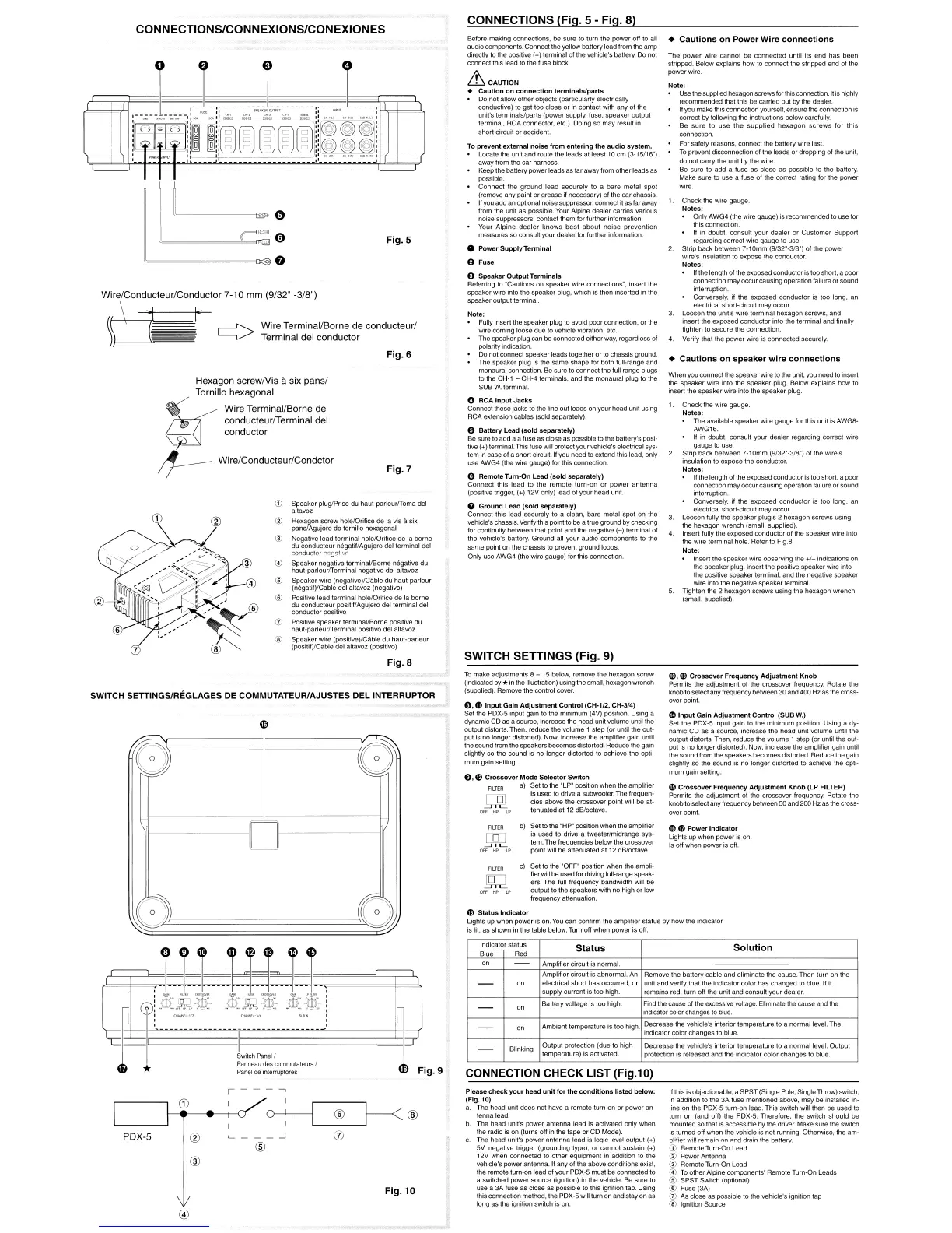
CONNECTIONS (Fig. 5 - Fig. 8)
To
prevent
external
noise
from
entering
the
audio
system.
Locate the unit and route the leads at least
10
cm
(3-15116")
away from the car harness.
Keep the battery power leads as far away from
other
leads as
possible
Connect
the
ground
lead
securely
to
a bare
metal
spot
(remove any paint
or
grease if necessary) of the
car
chassis.
If you
acid
an
optional noise suppressor, connect it as far away
from the unit as possible. Your Alpine dealer carries various
noise suppressors, contact them for
lurther
information.
Your
Alpine
dealer
knows
best
about
noise
prevention
measures so consult your dealer for further information.
o
Power
Supply
Terminal
a
Fuse
e
Speaker
Output
Terminals
Referring
to
"Cautions on speaker
wire
connections", insert the
speaker wire into the
speaker
plug, which is Ihen inserted in the
speaker output terminal.
Before making connections. be sure to turn the power off to all
audio components. Connect the yellow battery lead from the
amp
directly to the positive (+) terminal of the vehicle's battery.
Do
not
connect this lead to the fuse block
&
CAUTION
•
Caution
on
connection
terminals/parts
Do not allow
other
objects (particularly electrically
conductive)
to
get
too
close or in
contact
with any of the
unit's terminals/parts (power supply. fuse,
speaker
output
terminal, RCA connector. etc.). Doing so
may
result in
short
circuit
or
accident.
Note;
Fully insert the
speaker
plug to avoid poor connection,
or
the
wire coming loose
due
10
vehicle vibration, etc.
The
speaker plug can
be
connected either way, regardless of
polarity indication
Do
not connect speaker leads together
or
to chassis ground
The speaker ptug is the same shape for both full-range and
monaural connection.
Be
sure
10
connect the lull range plugs
to the
CH·l
- CH-4 terminals. and the monaural plug
to
the
SUB
W.
terminal.
o
RCA
Input
Jacks
Connect these lacks to the line out leads on your
head
unit using
RCA extension cables (sold separately)
o
Battery
Lead
(sold
separately)
Be
sure to add a a fuse as close as possible to the battery's posi-
tive (+) terminal. This fuse will protect your vehicle's electrical sys·
tem in case
of
a short circuit. If you
need
to extend this lead. only
use AWG4 (the wire gauge) for this connection.
o
Remote
Turn-On
Lead
(sold
separately)
Connect
this
lead
to
the
remote
turn-on
or
power
antenna
(positive trigger, (+)
12V
only) lead of your
head
unit.
G
Ground
Lead
(sold
separately)
Connect this lead securely
to
a clean. bare metal spot on the
vehicle's chassis. Verify this point to
be
a true ground
by
checking
for continuity between that point and the negative
(-)
terminal
01
the vehicle's battery. Ground all your
audio
components to the
same point on the chassis to prevent ground loops.
Only use AWG4 (the
wire
gauge) for this connection
SWITCH SETTINGS (Fig. 9)
To
make adjustments 8 - 15 below,
remove
the hexagon screw
(indicated by *in the illustration) using the small, hexagonwrench
(supplied). Remove the control cover.
0,
'-D
Input
Gain
Adjustment
Control
(CH.112, CH-314)
Set the PDX-5 input gain to the
minimum
(4V) position. Using a
dynamic
CD
as a source, increase the
head
unit volume until the
output distorts. Then, reduce the volume 1 step (or until the out-
put is no
longer
distorted). Now, increase the amplifier gain until
the sound from thespeakers becomes distorted. Reduce the gain
slightly so the sound is no longer distorted
to
achieve the opti-
mum gain setting.
0,0
Crossover
Mode
Selector
Switch
FILTER
a)
~et
to the "LP" position when the amplifier
IS used to drive a subwoofer. The frequen·
~
..J,~
~
cies above the crossover point will
be
at-
u.-
.--.-
LC
tenuated at 12 dB/octave.
Fig.7
Fig. 6
Fig.S
Wire Terminal/Borne de conducteurl
Terminal del conductor
I·
Dr-----
Fig.8
G)
Speaker plug/Prise
du
haut-parleurfToma del
altavoz
@
Hexagon
screw hole/Orifice
de
la
vis
asix
panslAgujero
de
tornillo hexagonal
@ Negative lead terminal hOle/Orifice
de
la
borne
du
conducleur
negatillAgujero del terminal del
condllctor
"C:OJ.~j
..n
@ Speaker negative terminal/Borne negative
du
haul-parleurfTerminal negativQ del altavoz
®
Speaker
wire
{negative)/Cable
du
haut-parleur
(negatil)/Cable de! altavoz (negativo)
® Positive lead terminal hole/Orifice de la borne
du conducteur positil/Agujero del terminal del
conductor
positive
o Positive
speaker
terminal/Borne positive
du
haul-parleur~erminal
positivo del allavoz
® Speaker wire (positive)/Cable
du
haul-parleur
(posilif)/Cable del altavoz (positivo)
Hexagon
screwNis
asix
pansl
Tornillo hexagonal
G(
~
Wire Terminal/Borne de
. conducteurlTerminal del
__
conductor
'jJ
;f------
Wire/Conducteur/Condctor
o
c""':
0
~~~~~~=O&:§O
CONNECTIONS/CONNEXIONS/CONEXIONES
Wire/Conducteur/Conductor 7-10 mm (9/32" -3/8")
~~
\
SWITCH SETTINGS/REGLAGES
DE
COMMUTATEUR/AJUSTES DEL INTERRUPTOR
FILTER
~~p
c) Set to the "OFF" position
when
the ampli-
fier will be used fordriving fUll-range speak-
ers.
The
full Irequency bandwidth will be
output to
the
speakers with
no
high or low
frequency attenuation.
U)
Status
Indicator
Lights up
when
power
is on.
You
can
confirm the amplifier status by
how
the indicator
is lit. as shown in the table below. Turn off when
power
is off.
CONNECTION CHECK LIST
(Fig.l0)
Indicator status
Blue Red
Blinking
Status
Amplifier circuit is normal.
Amplifier circuit is abnormal. An
electrical
short
has
occurred,
or
supply
current is
too
high.
Batlery
voltage is too high
Ambient temperature is
too
high
Output
protection (due
to
high
temperature) is activated.
Solution
Remove the battery cable and eliminate the cause. Then turn on the
unit and verify thaI the indicator color
has
changed
10
blue.
If
it
remains red, turn
off
the unit and consult
your
dealer.
Find the cause of the excessive voltage. Eliminate the cause and the
indicator color changes to blue
Decrease the vehicle's interior temperature to a normal level.
The
indicator color
changes
to blue.
Decrease
the vehicle's interior temperature to a normal level. Output
protection is released and the indicator color
changes
to blue
,
eD
I
0-+--1
~®
®
PDX-5
®
__
..J
(j)
®
@
Fig.10
@
Please
check
your
head
unit
for
the
conditions
listed
below:
(Fig. 10)
a. The
head
unit does not have a remote
tum-on
or power an-
tenna lead
b The
head
unit's power antenna lead is activated only when
the radio is on (turns
off
in the tape
or
CD
Mode).
c.
The head
Ilnifs
powAr
~ntenna
lead is logic level output (
...
)
5V.
negative trigger (grounding type), or cannot sustain (+)
12V when connected
to
other equipment in addition to the
vehicle's power antenna.
1/
any
of
the above conditions exist,
the remote turn-on lead of
your
PDX·5
must
be connected
to
a switched power source (ignition) in the vehicle. Be sure to
use a
3A
fuse as close as possible to this ignition tap. Using
this connection method. the PDX-5 will turnon and stay on as
long as the ignition switch is on
Ifthis is objectionable. a
SPST
(Single Pole, Single Throw) switch,
in addition to the
3A
fuse mentioned above,
may
be
installed in-
line on the PDX-5 turn-on lead.
This
switch will then be
used
to
turn on (and off) the PDX-5. Therefore. the switch
should
be
mounted so that is accessible
by
the driver. Make sure the switch
is turned off when the vehicle is not running. Otherwise, the am-
plifier wil! remain
nn
And
drilin
the l)iltlerv.
ill
Remote Turn-On Lead
® Power Antenna
@ Remote Turn-On Lead
@ To
other
Alpine components' Remote Turn·On Leads
@
SPST
Switch (optional)
®
Fuse(3A)
(f) As close as possible to the vehicle's ignition tap
® Ignition Source
 Loading...