SYSTEM DIAGRAMS
Before making a connection, check
the
total
number
of
impedance
of
the
speaker connected
to
the
unit.
If
you have any questions,
contact
the
nearest Alpine dealer.
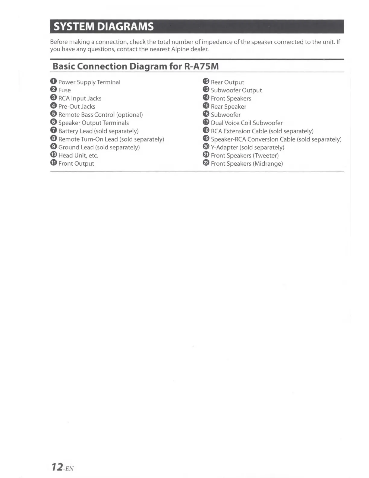
Basic Connection Diagram for R-A75M
0 Power Supply Terminal
8Fuse
0
RCA
Input
Jacks
0 Pre-Out
Jacks
0 Remote
Bass
Control (optional)
0 Speaker OutputTerminals
G Battery Lead (sold separately)
0 Remote Turn-On Lead (sold separately)
0 Ground Lead (sold separately)
~
Head Unit, etc.
4D
Front
Output
12
-EN
CB
Rear
Output
Ci)
Subwoofer
Output
m Front Speakers
C0
Rear
Speaker
~
Subwoofer
'8 Dual Voice Coil Subwoofer
G)
RCA
Extension Cable (sold separately)
C0
Speaker-RCA Conversion Cable (sold separately)
f)
Y-Adapter (sold separately)
fD
Front Speakers (Tweeter)
@)
Front Speakers (Midrange)