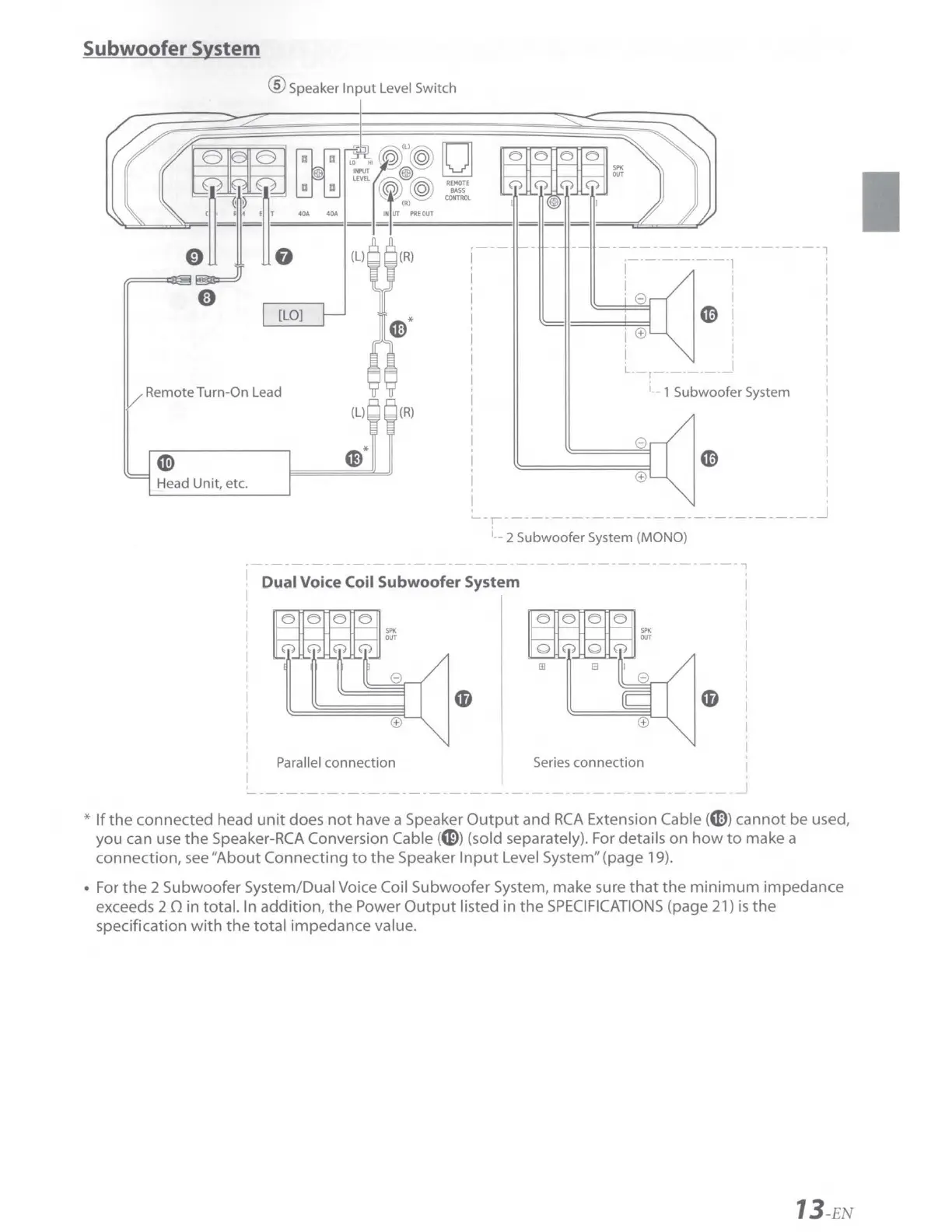
Subwoofer System
@ Speaker
Input
Level Switch
----------------------7
,------------1
I .
[LO]
V Remote Turn-On Lead
(L)
~
Head Unit, etc.
(R)
. I
I .
'8
I
===1====1
C0
i
i,
(f)
I
i
! i
L--1---------
i
__
1 Subwoofer System
8
(f)
~-r-------------------------------~
i
__
2 Subwoofer System (MONO)
----------------7
Dual
Voice Coil Subwoofer System
! Parallel connection Series connection I
I ,
'-----------------------------------------------~
*
If
the
connected head
unit
does
not
have a Speaker
Output
and
RCA
Extension Cable
(CE))
cannot be used,
you can use
the
Speaker-RCA Conversion Cable (
G))
(sold separately). For details
on
how
to
make a
connection,
see
"About Connecting
to
the
Speaker
Input
Level System" (page 19).
• For
the
2 Subwoofer System/Dual Voice Coil Subwoofer System, make sure
that
the
minimum
impedance
exceeds 2 0 in total. In addition,
the
Power
Output
listed in
the
SPECIFICATIONS
(page 21)
is
the
specification
with
the
total
impedance value.
13-
EN