Main
Vehicle
Battery
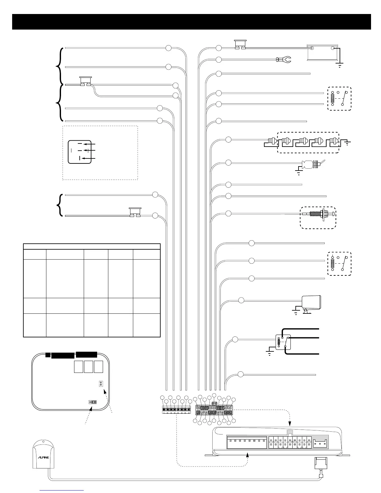
Yellow ~ Battery
White /Brown ~ Door Lock Common (30)
Brown/Blue ~ Door Lock N/C (87A)
Brown/Red ~ Door Lock N/O (87)
Green/Red ~ Door Unlock N/O (87)
White/Green ~ Door Unlock Common (30)
Green/Blue ~ Door Unlock N/C (87A)
Normally Open (N/O)
Normally Closed (N/C)
Common
White ~ Parking Light Flash N/O (87)
Yellow/White ~ Parking Lt. Comm (30)
5 Amp Fuse (MAX)
10 Amp Fuse
20 Amp Fuse
Black - Ground
Red ~ Ignition (N/O Starter Must be True Ignition)
Black/White ~ Alarm Disable Input (-)
Yellow/Red ~ LED ( +)
Red/White ~ Valet Input (—)
Brown/White ~ Door Input (+ or —)
Blue/Green ~ Digital Pager Output
Blue/Yellow ~Dome Light Surveillance (—) 200mA
Yellow/Black ~ EXT-2 (—) 200mA
(1-Second or Latched Output)
Yellow/Brown ~ EXT-3 (—) 200mA
(Continuous or 1-Second Output)
Blue ~ Siren (+) 1.5 Amps Max
Orange ~ Starter Cut Relay
(+) 200mA
Blue/White ~ Armed Output (—) 200mA
Optional (5 LED’s Max)
Optional
To Key (30)
Use for
Normally Open
(87)
Use for
Normally Closed
(87A)
Red / Yellow
Red / White
Red
Optional
Relay
Optional
30
87
87a
Input wires for
the internal
Door Lock
Relay
Input wires for
the internal
Door Unlock
Relay
Input wires for
the internal
light flash relay
Standard Relay
For Reference
The coil contacts (85 & 86) are not needed
they are controlled within the main unit
13B
A
C
E
D
H
G
5
White/Blue ~ Optional Priority Door Unlock (-) 200mA
10
8
4
1
11
12
3
6
Yellow/Green ~ EXT-1 (—) 200mA
(1-Second or Latched Output)
15
16
18
7
F
Disarm/Valet
Switch
Part No.
01V91400F82
Siren
Part No.
50T55282W01
Starter Cut Relay
Part No.~ 80T25274W01
Green/White ~ Hood/Trunk Input (—)
2
14
Electronic Impact Sensor (Included)
5A
20A
10A
To SEC-8205
Digital Pager
(Optional)
1
10
12
14
18
4
3
8
9
7
11
13
15
17
2
6
5
16
A
G
C
B HFD
E
HGFEDCBA
ELECTRONIC
IMPACT SENSOR
Connect grounding output
from optional remote
start module to disable
ignition and impact trigger.
JP1
OFFON
P4
1
2
JP1 ~ Selectable Starter Disable
ON = Normally Open
OFF = Normally Closed
P4 ~ Infrared Audio
Interface Connector
Function Setup
Sensor Setup
EXT Setup
Feature
Chirp Select
Auto Lock
Ignition Lock
Ignition Unlock
Arming Type
Siren Duration
Door Lock Pulse Length
Panic Arm
2-Car Operation
Double Pulse Door Unlock
Priority Door Unlock
Door Sensor Input
Door Sensor Polarity
Hood/Trunk Sensor Input
Impact Sensor Input
EXT-1 Output Configuration
EXT-2 Output Configuration
EXT-3 Output Configuration
EXT-1 Impact/IGN Disable
EXT Trunk/Impact Cancel
EXT Trunk/Impact Select
Siren will Chirp
Twice Indicating...
Off
On
On
On
Auto
60 Seconds
3 Second
On
Car #2
On
On
Off
Positive
Off
Off
Latched
Latched
1 Second
On
Off
EXT-3
Siren will Chirp
Once Indicating...
On
Off
Off
Off
Manual
30 Seconds
1 Second
Off
Car #1
Off
Off
On
Negative
On
On
1 Second
1 Second
Continuous
Off
On
EXT-2
Feature Programming Chart
LED Will Blink...
1 Short
2 Short
3 Short
4 Short
1 Long
1 Long 1 Short
1 Long 2 Short
1 Long 3 Short
1 Long 4 Short
2 Long
2 Long 1 Short
1 Short
2 Short
3 Short
4 Short
1 Short
2 Short
3 Short
4 Short
1 Long
1 Long 1 Short
SEC-8028 Wiring Diagram
Mode
9
Note: For best results, mount the impact sensor flat
against a solid-vertical mounting surface. Avoid
using a tie-strap to secure to a wire harness.
Rev. 1/28/00
SEC-8028
Installation Instructions (English)
Page 4
 Loading...