pag. 34
MDE/C133 2561 001
MX3IPG2A
tab. E
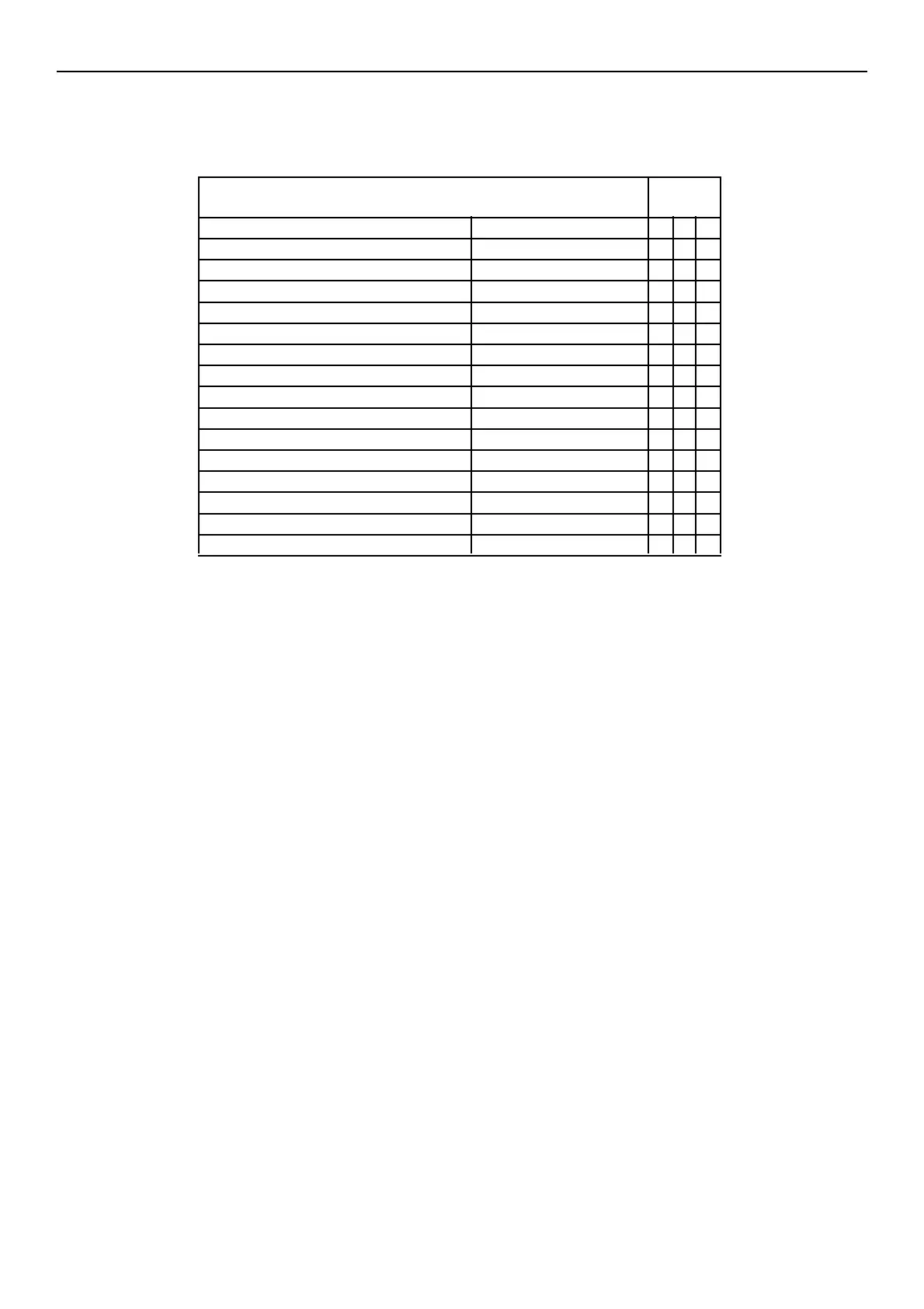
CONTROL MATRIX DIGITAL
INPUTS
DESCRIPTION FUNCTION 1 2 3
input enabled by normal de-energizing
first underres. threshold trip lock BLOC. R<
sec. underres. threshold trip lock BLOC. R<<
overcurrent threshold trip lock BLOC. I~>
overvoltage threshold trip lock BLOC. U~>
undervoltage threshold trip lock BLOC. U~<
first dir. underv. threshold trip lock BLOC.U-<
sec. dir. underv. threshold trip lock BLOC.U-<<
first dir. overv. threshold trip lock BLOC.U->
sec. dir. overv. threshold trip lock BLOC.U->>
timer tX1 start t_X1
timer tX2 start t_X2
timer tX3 start t_X3
switching to spare settings SETTINGS SWITCH / /
reset LED's and output relays RESET (LED+Xmem) / /
/ not to be allocated