Do you have a question about the Altec Lansing 2200 POWER AMPLIFIER and is the answer not in the manual?
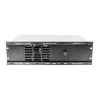
Overview of the ALTEC Incremental Power System's modular design and capabilities.
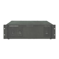
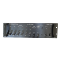
The central chassis that houses plug-in modules for the Incremental Power System.
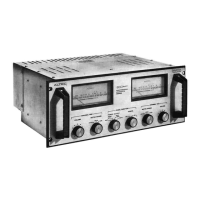
Modules that process balanced or unbalanced audio signals into the system.
Modules that condition signals for power amplifiers, enabling various frequency splits.
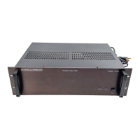
Modules providing 75W (2275) or 150W (2276) output, combinable for various configurations.
Requirements for adequate airflow to prevent overheating of the system.
Procedures for rack mounting and shelf mounting the main frame.
Steps for inserting input, driver, and power amplifier modules into the main frame.
Details on power input, voltage strapping, and 8-ohm conversion.
How to connect balanced and unbalanced audio sources to the system.
How to connect speakers and distribute signals from amplifier outputs.
Setup for 70-volt and 25-volt systems using various amplifier configurations.
Configuring modules to drive individual loudspeaker loads.
Combining modules to increase output power for low-impedance loads.
Connecting two modules out-of-phase to drive higher impedance loads or 70-volt lines.
Combining parallel and bridged modes for high-power 70-volt applications.
Assigning input signals and routing driver outputs to power amplifiers.
Controls for enabling bridged modes and adjusting signal levels.
Configuring the Model 2251 for two-way or three-way frequency splitting.
Essential safety and operational guidelines for the Incremental Power System.
| Brand | Altec Lansing |
|---|---|
| Model | 2200 POWER AMPLIFIER |
| Category | Amplifier |
| Language | English |