83
NO
DK
FI
SE
FR
GB
GB
4. Align the installation bottom horizontally.
5. Mark two diagonally opposite bore holes using the installation bottom (see
page 7 fig. 2a).
If wood walls are present, the screws can be screwed directly into the wood.
Pre-drilling with a 1.5 mm wood drill can facilitate the installation of the screws.
6. For stone walls, drill the holes at the marked positions with a 5 mm masonry
drill.
7. Insert dowels into the bores.
8. Install the installation bottom using the supplied screws (see page 6 fig. 2a).
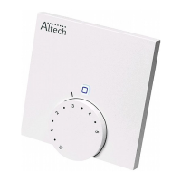
9. Position the room control unit Analog onto the installation bottom and latch it in
(see page 7 fig. 3).
5.2.2 Installation in flush-type box
The fixing holes on the installation bottom can be used for installation on a flush-
type box (see page 6 fig. 2b).
1. If necessary, release the device from the installation bottom with a suitable
screwdriver (see page 7 fig. 4).
2. Align the installation bottom horizontally on the flush-type box.
3. Install the installation bottom with suitable screws (see page 6 fig. 2b).
4. Position the room control unit Analog onto the installation bottom and latch it
into the clips (see page 7 fig. 3).