2–2 Chapter 2: USB-Blaster Specifications
USB-Blaster Connections
USB-Blaster Download Cable User Guide © April 2009 Altera Corporation
Cable-to-Board Connection
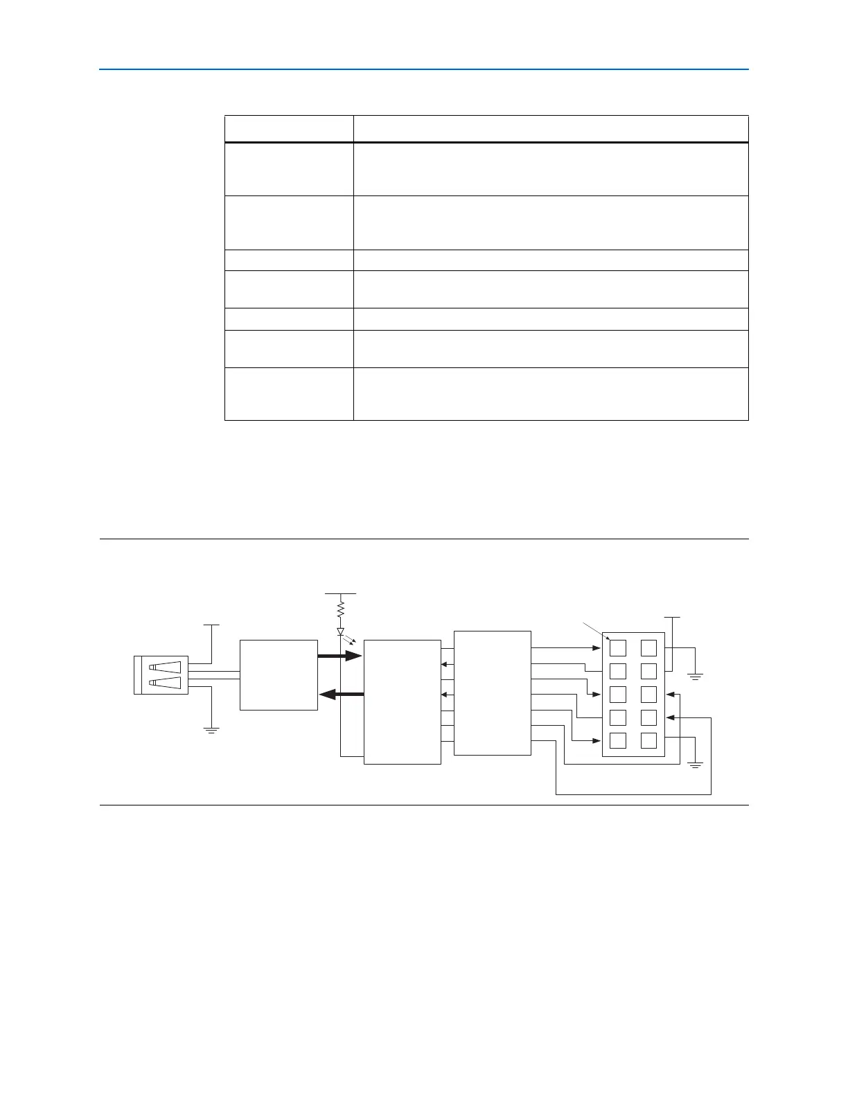
A standard USB cable connects to the USB port on the device. Figure 2–1 shows a
block diagram of the USB-Blaster download cable.
Cyclone II, Cyclone,
APEX II, APEX 20K,
and Mercury devices
As specified by V
CCIO
FLEX 10K, FLEX 8000,
and FLEX 6000
devices
5 V
FLEX 10KE device 2.5 V
FLEX 10KA and FLEX
6000A devices
3.3 V
EPC2 devices 5 V or 3.3 V
EPC4, EPC8, and
EPC16 devices
3.3 V
EPCS1, EPCS4,
EPCS16, EPCS64, and
EPCS128 devices
3.3 V
Table 2–1. USB-Blaster VCC(TRGT) Pin Voltage Requirements (Part 2 of 2)
Device Family USB-Blaster VCC Voltage Required
Figure 2–1. USB-Blaster Block Diagram
USB Interface
Chip
EPM7064AETC44
I/Os
I/Os
V
CC (TRGT)
Pin 1
V
CC
I/O
I/O
I/O
I/O
I/O
I/O
I/O
I/O
USBVCC
USB
Receptacle
10-Pin
Female Plug
Voltage Translator
Circuitry