Chapter 2: USB-Blaster Specifications 2–5
Operating Conditions
© April 2009 Altera Corporation USB-Blaster Download Cable User Guide
Operating Conditions
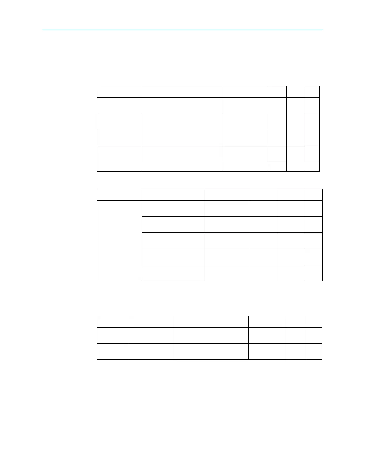
Table 2–3 through Table 2–5 summarize the maximum ratings, recommended operating
conditions, and DC operating conditions for the USB-Blaster cable.
Table 2–3. USB-Blaster Cable Absolute Maximum Ratings
Symbol Parameter Conditions Min Max Unit
V
CC(TRGT)
Target supply voltage With respect to
ground
–0.3 5.5 V
V
CC(USB)
USB supply voltage With respect to
ground
–0.5 6.0 V
I
I
Input current TDO or
dataout
–10.0 10.0 mA
I
o
Output current for Rev. A and
Rev. B cable
TCK, TMS,
TDI, nCS,
nCE
–20.0 20.0 mA
Output current for Rev. C cable –50.0 50.0 mA
Table 2–4. USB-Blaster Cable Recommended Operating Conditions
Symbol Parameter Conditions Min Max Unit
V
CC(TRGT)
Target supply voltage,
5.0-V operation
— 4.75 5.25 V
Target supply voltage,
3.3-V operation
—3.03.6V
Target supply voltage,
2.5-V operation
— 2.375 2.625 V
Target supply voltage,
1.8-V operation
— 1.71 1.89 V
Target supply voltage,
1.5-V operation (1)
— 1.43 1.57 V
Note to Table 2–4:
(1) This operating condition can be applicable to USB-Blaster Cable (Rev. A & B)
Table 2–5. USB-Blaster Cable (Rev. A & B) DC Operating Conditions
Symbol Parameter Conditions Min Max Unit
V
IH
High-level input
voltage
—V
CC(TRGT)
–0.2 V
V
IL
Low-level input
voltage
—0.15V