2–4 Chapter 2: USB-Blaster Specifications
USB-Blaster Connections
USB-Blaster Download Cable User Guide © April 2009 Altera Corporation
1 The circuit board must supply V
CC(TRGT)
and ground to the USB-Blaster
cable for the I/O drivers.
Circuit Board Header Connection
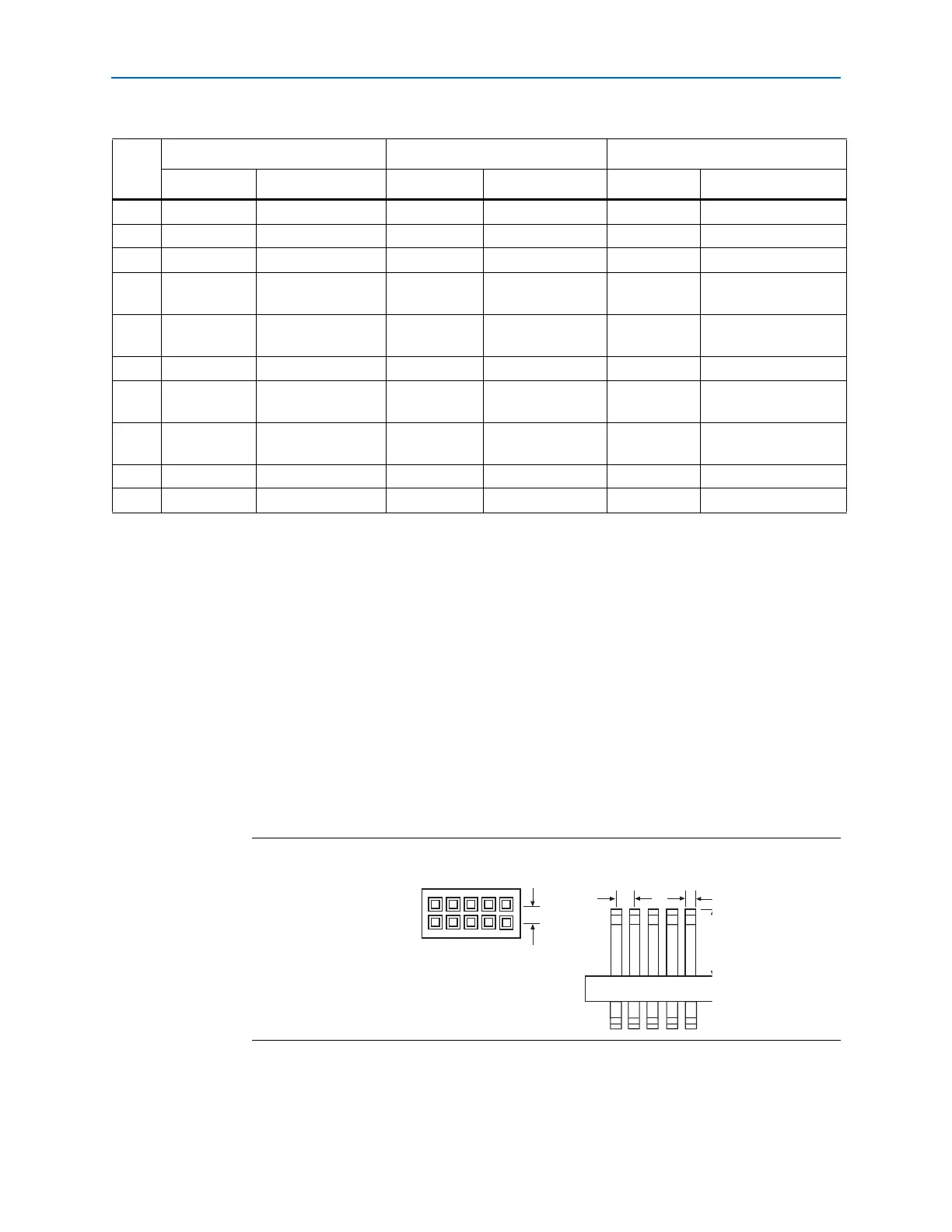
The circuit board's 10-pin male header, which connects to the USB-Blaster cable's
10-pin female plug, has two rows of five pins. These pins are connected to the device’s
programming or configuration pins. Figure 2–4 shows the dimensions of a typical
10-pin male header.
1 Although a 10-pin surface mount header can be used for the JTAG, AS or PS
download cable, Altera recommends using a through-hole connector because of the
repeated insertion and removal force needed.
Table 2–2. USB-Blaster Female Plug Signal Names & Programming Modes
Pin
AS Mode PS Mode JTAG Mode
Signal Name Description Signal Name Description Signal Name Description
1 DCLK Clock signal DCLK Clock signal TCK Clock signal
2 GND Signal ground GND Signal ground GND Signal ground
3 CONF_DONE Configuration done CONF_DONE Configuration done TDO Data from device
4 VCC(TRGT) Target power supply VCC(TRGT) Target power
supply
VCC(TRGT) Target power supply
5 nCONFIG Configuration
control
nCONFIG Configuration
control
TMS JTAG state machine
control
6 nCE Cyclone chip enable — No connect — No connect
7 DATAOUT Active serial data
out
nSTATUS Configuration
status
— No connect
8 nCS Serial configuration
device chip select
— No connect — No connect
9 ASDI Active serial data in DATA0 Data to device TDI Data to device
10 GND Signal ground GND Signal ground GND Signal ground
Figure 2–4. 10-Pin Male Header Dimensions
0.025 S
0.100
Side View
0.100
Top View
Dimensions are shown in inches