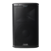
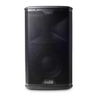
EasyManua.ls Logo

Alto Professional BLACK 12 - User Manual

Alto Professional BLACK 12
57 pages
Print Icon
To Next Page IconTo Next Page
Loading...
Service Manual
BLACK 12
Version: A7
Date: 2013/12/19
Specifications
Amplifier: Tweeter:
Power Source .................... AC 90V-240V/50Hz-60Hz Impedance ............................................................. 8Ω
Power Handling ........................................... 120 Watt
Power Consumption .................................. 1500 Watt
Sensitivity ........................................................ 110 dB
Output Power ................ 400 W(Set)+800 W(Woofer)
Frequency ........................................................ 2 kHz
(THD 1%, Without Limiter)
Woofer:
Frequency Response ....................Sat 1.5kHz~20kHz
Impedance .............................................................
Woofer 50Hz~1.5kHz
Power Handling ........................................... 350 Watt
Sensitivity ........................................................ 99 dB
Frequency ........................................................ 1 kHz
Dimensions ............. 354(W)x371.5(D)x610.6(H) m/m
Specifications subject to change in order to accommodate improvement in design.

Questions and Answers

Summary

Specifications

Amplifier Specifications

Details amplifier power source, consumption, output power, and frequency response.

Tweeter Specifications

Lists tweeter impedance, power handling, sensitivity, and frequency.

Woofer Specifications

Specifies woofer impedance, power handling, sensitivity, and frequency.

Block Diagram

System Interconnections

Illustrates signal flow and component connections within the audio system.

Troubleshooting Guide

Turn-on Issue

Provides causes and remedies for issues preventing the unit from powering on.

No Sound

Outlines troubleshooting steps for audio output problems.

Audio Distortion

Offers solutions for distorted audio output.

Bluetooth Disconnected

Lists steps to resolve Bluetooth connectivity issues.

APP No Response

Addresses problems with application responsiveness.

Low Sound

Provides solutions for low audio volume.

Machine Cannot Be Updated

Details troubleshooting for software update failures.

Wiring Diagram

Component Connections

Shows the physical and electrical connections between internal PCBs and external components.

ADC Schematic

Analog-to-Digital Converter

Details the AK5388 ADC chip and its associated circuitry.

Bluetooth Schematic

Bluetooth Module

Illustrates the MFI341S2162 and MFI337S3959 Bluetooth ICs and connections.

Buffer PWA Schematic

Buffer Amplifier Circuits

Shows operational amplifiers used for signal buffering.

DAC Schematic

Digital-to-Analog Converter

Details the AK4396 DAC chip and its associated circuitry.

Digital Main Schematic

Microcontroller and DSP Interface

Shows connections between MCU, DSP, and Bluetooth modules.

DSP Schematic

Digital Signal Processor

Details the ADAU1701 DSP chip and its peripheral connections.

MCU Schematic

Microcontroller Unit

Illustrates the LPC1227FBD48 microcontroller and its I/O connections.

Analog Input Processing

Signal Conditioning Circuitry

Illustrates transistor and diode circuits for analog signal conditioning.

Driver and Output Stages

Speaker Output Connections

Shows how the amplifier outputs connect to the woofer and tweeter.

HF Amplifier Stage (Channel -)

IRS2092 HF Driver Circuit

Details the IRS2092 IC and associated driver components for the HF channel.

HF Amplifier Stage (Channel +)

IRS2092 HF Driver Circuit

Details the IRS2092 IC and associated driver components for the HF channel.

Woofer Amplifier Stage (Channel -)

IRS2092 Woofer Driver Circuit

Details the IRS2092 IC and associated driver components for the woofer channel.

Woofer Amplifier Stage (Channel +)

IRS2092 Woofer Driver Circuit

Details the IRS2092 IC and associated driver components for the woofer channel.

Outputs Circuitry

PWA Board Connections

Shows connections to the PWA WF and PWA HF boards.

Pre-Power Supply

Voltage Regulation and Control

Illustrates the MC34063 and TL431 based voltage regulation circuits.

HF Power Amplifier Board

IRS2092 HF Amplifier Channels

Depicts the driver circuitry for the high-frequency amplifier channels.

Woofer Power Amplifier Board

IRS2092 Woofer Amplifier Channels

Depicts the driver circuitry for the woofer amplifier channels.

Auto Function Circuit

Signal Detection and Control

Shows circuitry related to automatic signal detection or standby control.

Auto_08 S Circuit

Operational Amplifier Configurations

Illustrates LM324 operational amplifier circuits for signal processing.

Bluetooth Control Circuit

Pairing Button and LED

Details the circuitry for the Bluetooth pairing button and indicator LED.

I;O Preamp Main Board

Line and Microphone Inputs

Shows input connectors and associated signal processing circuitry.

DSP Interface

Illustrates the connection interface for the Digital Signal Processor.

Control Signal Routing

Depicts signal paths for Auto, Logo, and Bluetooth control.

Line Input Circuit

Variable Gain Control

Shows circuitry for variable gain control on line inputs.

Mute Function Circuit

Audio Muting Transistor Stages

Illustrates transistor circuits used for audio muting.

DSP Control Interface

Analog Multiplexer and Control Logic

Shows the 4051B multiplexer and associated control signals.

Variable Line Input Circuit

Gain and Level Adjustment

Details circuitry for adjusting line input gain and level.

HF Power Supply Filtering

Inductor Filtering Network

Shows a simple filter with inductors for power lines.

Main Power Output Stage

MOSFET Driver Circuits

Illustrates the MOSFET driver circuitry for the power output stage.

PWA Main Board Connections

Power and Signal Routing

Depicts the main power and signal distribution on the PWA board.

High Frequency Power Supply

Transistor-Based Regulation

Shows transistor circuits used for power supply regulation.

AC Power Filter

EMI Filtering Circuit

Details the components and layout of the EMI filter board.

5573 A Power Stage

Power Conversion and Output

Illustrates the power conversion and output components of the 5573A stage.

5573 A PFC Control

Power Factor Correction Circuit

Details the UCC2819D PFC controller and related components.

5573 A Bias Supply

Voltage Regulation and Bias Generation

Shows the LP2951ACM and TL431 for bias voltage generation.

5573 A Microcontroller

ATtiny461 A Microcontroller

Illustrates the ATtiny461A microcontroller and its peripheral connections.

5573 A Secondary Power Supplies

DC-DC Conversion Circuits

Details the DC-DC converter ICs (LM237) for generating secondary voltages.

5573 A Power Good Signal

Power Status Monitoring

Shows the MC33161D for monitoring power supply status.

5573 B Power Stage

Power Conversion and Output (5573 B)

Illustrates the power conversion and output components of the 5573B stage.

Exploded View - Overall Unit

Component Identification

Provides a visual breakdown of the speaker's physical components with reference numbers.

Power Amplifier Exploded View

Power Amplifier Components

Shows a detailed breakdown of the power amplifier section's parts.

Tweeter Exploded View

Tweeter Assembly Components

Details the individual parts that make up the tweeter assembly.

Woofer Exploded View

Woofer Assembly Components

Details the individual parts that make up the woofer assembly.

Mechanical Parts List

Hardware and Chassis Components

Lists screws, handles, logos, and chassis parts with part numbers and quantities.

Power Amplifier Parts List (Part 1)

PCB and Mounting Hardware

Lists PCBs, screws, spacers, and mounting brackets for the power amp.

Power Amplifier Parts List (Part 2)

Cables, Connectors, and Accessories

Lists wire combinations, nylon ties, panel labels, knobs, and sleeves.

Tweeter Parts List

Tweeter Magnet and Diaphragm

Lists the magnet system, diaphragm system, and back cover for the tweeter.

Woofer Parts List

Woofer Diaphragm and Magnet

Lists the diaphragm system and magnet system for the woofer.

DSP P.C. Board Layout

Top and Bottom Views

Shows the component placement on both the top and bottom sides of the DSP PCB.

Driver P.C. Board Layout

Top and Bottom Views

Shows the component placement on both the top and bottom sides of the Driver PCB.

I;O-Preamp P.C. Board Layout

Top and Bottom Views

Shows the component placement on both the top and bottom sides of the I/O-Preamp PCB.

Power Amp P.C. Board Layout

Top and Bottom Views

Shows the component placement on both the top and bottom sides of the Power Amp PCB.

Power Supply P.C. Board Layout (5573_A)

Top and Bottom Views

Shows the component placement on both sides of the 5573_A Power Supply PCB.

Power Supply P.C. Board Layout (5573_B)

Top and Bottom Views

Shows the component placement on both sides of the 5573_B Power Supply PCB.

Filter and Logo Board Layouts

EMI, DC Filter, and Logo PCB Views

Presents top and bottom views of the EMI Filter, DC Filter, and Logo PCBs.

Alto Professional BLACK 12 Specifications

General IconGeneral
BrandAlto Professional
ModelBLACK 12
CategorySpeakers
LanguageEnglish

Related product manuals