4
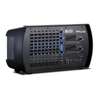
MASTER I/O (INPUT/OUTPUT)
19. AMPLIFIER Mode Switch- This
switch provides three modes:
MAIN/MAIN, MAIN/MONITOR and
BRIDGE. Select any one of these
modes to route the signals to the
corresponding jacks according to the
speaker panel connection. This switch
only affects the rear panel outputs.
The front panels outputs are
unaffected by this switch.
• MAIN/MAIN- When the switch is set to this, the amp will send the main mix to the rear panel Speakon*
jacks or
the rear panel ¼” jacks.
• MAIN/MON- When the switch is set to this, the amp will send the main mix to the OUTPUT 1 Speakon
jack and 1/4'”jack. The monitor mix will be sent to the OUTPUT 2 Speakon jack.
• BRIDGE- When the switch is set to this, the amp will send the main mix to the rear panel OUTPUT 2
Speakon jack.
20. MAIN OUTPUTS – These 1/4" line level outputs can be connected to powered speakers or an amplifier
system. The level of these outputs is controlled by the Main Level knob.
21. MONITOR OUTPUT- This line level balanced output is used to connect the input of an external amplifier or
powered speaker.
22. PHONES – Connect your 1/4" stereo headphones to this output.
23. 2-TRACK INPUTS – Connect these to the outputs of an external sound source using standard stereo RCA
cables (sold separately). You can send this to channels 9/10 (using the 2-TRACK to 9/10 switch) or to the
main outputs (using the 2-TRACK TO MAIN switch).
24. 2-TRACK OUTPUTS – You may connect these outputs to the inputs of an external recording device using a
standard stereo RCA cable (sold separately).
25. AUX OUT- This outputs the line level signal sent from a channel’s AUX1 Pre knob to the Monitor Output. You
can use it to feed the inputs of another stereo multi-effects unit (using a Y-type cable sold separately).
26. STEREO RETURN- This stereo jack is used to route a stereo signal to the Main, Monitor and Phones outputs
by adjusting the FX TO MAIN and FX TO MON knobs.
27. 2-TRACK TO– If you position this switch to the left you will route the signal fed into the TAPE IN sockets into
CH9~10 path, and the signal will be affected by channel level control, channel EQ, DSP send, and MAIN level
control. Positioning this switch to the right will route the TAPE IN signal into Main mix bus. In this case signal
will be affected only by Main level control.
* Speakon is a trademark of Neutrik® AG, registered in the U.S. and other countries.
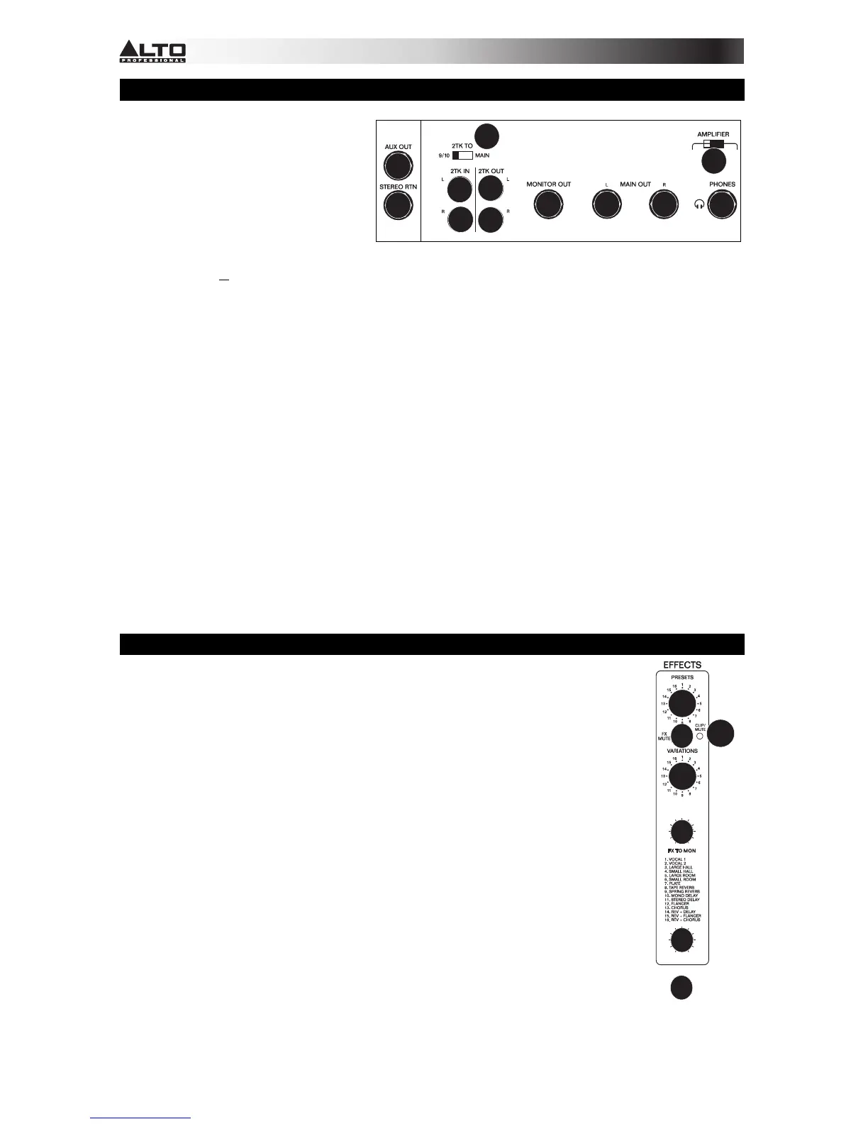
DSP (DIGITAL SIGNAL PROCESSOR)
28. EFFECTS SELECTOR – Selects the effect that the mixer's internal effects processor will
apply to the various channels. Each channel can send different levels of audio to the
processor by adjusting their Aux 2/FX Post knobs.
29. FX MUTE – Press this button to mute/unmute the effects.
30. VARIATIONS SELECTOR – Selects the amount of the effect applied to the various
channels.
31. Clip/Mute LED- This LED flashes when the signal input into the digital multi-effect is too
strong. When the digital effect module is muted, the LED also lights up.
32. FX TO MON- This is used to control the volume of the processed signal sent to Monitor mix,
which can be varied from - to +10dB.
33. FX TO MAIN- This is used to control the volume of the processed signal sent to Main mix
bus, which can be varied from - to+10dB.
34. FOOTSWITCH – When a latching-style footswitch is connected to this jack with a 1/4" TRS
cable, it can be pressed to allow all channels to bypass the mixer's internal effects
processor.
20 20
21 22
23
23
24
24
25
26
27
19
FOOTSWITCH
 Loading...