Do you have a question about the Alto S-6 and is the answer not in the manual?
Symbols for risk of electric shock, protective ground, and hazardous live terminals.
Definitions for WARNING (death/injury) and CAUTION (product damage) precautions.
Ensure correct voltage, unplug during storms or when unused.
Use insulated cabling and consult an electrician if unsure.
Do not remove covers; high voltages present; service by qualified personnel only.
Use correct fuse type and replace only when power is OFF and disconnected.
Ensure grounding before powering on; never alter ground wiring.
Install per instructions, avoid liquids, heat, and ventilation blockages.
Do not tamper with cord/plug; ensure proper fit and protect from stress.
Clean with dry cloth; refer servicing to qualified personnel.
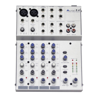
Overview of the S-6 as a compact, high-performance 6-channel mixer.
Highlights include ultra-low noise preamps, 3-band EQ, aux send, and LED metering.
Steps for connecting the AC adapter and power, and initial control settings.
Details on connecting microphones and line-level instruments to channels 1 and 2.
Description of stereo input channels 3-6 and mono operation.
Explanation of the 3-band equalizer (Hi, Mid, Low) and Panorama controls.
Description of the Auxiliary send control and signal returns.
Function of the Level control and Peak LED indicator for signal monitoring.
Controls for main mix level, headphones, control room, and tape I/O.
Operation of the +48V Phantom Power switch and status LEDs.
Description of main mix output, 2-track I/O, aux sends, phones, and control room outputs.
The main power ON/OFF switch and the 18VAC adapter connection point.
Turn down gains, set amp/monitor levels, and EQ/Pan to center.
Adjust input gain until Peak LED blinks occasionally for optimal headroom.
Repeat gain staging for all channels, adjust main mix level as needed.
Schematics for connecting unbalanced equipment to balanced jacks and XLRs.
Wiring diagrams for 1/4" stereo (TRS) and mono (TS) jack plugs.
Wiring diagrams for 3-pin XLR male plugs and line sockets.
Details on input/output impedances, equalization, and power supply.
Instructions for warranty registration and product return procedures.
Covers warranty period, limitations, and exclusions for defects.
| Channels | 6 |
|---|---|
| USB Interface | No |
| Effects | No |
| Type | Analog |
| Microphone Inputs | 2 |
| Line Inputs | 4 |
| Other Outputs | Headphone Output |
| Aux Sends | 1 |
| Phantom Power | Yes |
| Weight | 1.2 kg |