www.altronicinc.com
3
INSTALLATION INSTRUCTIONS
4.3 Operating temperature range is −40°F to 158°F (−40°C to 70°C). Humid-
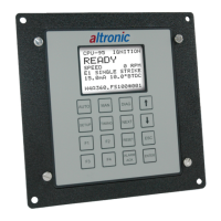
ity specication is 0-95%, non-condensing. Housed in an aluminum
weatherproof enclosure, the CPU-95 Display Module is splash resis-
tant; however, the mounting site should provide as much protection
from inclement weather as is practical. Avoid mounting the LCD
display and keypad in direct sunlight.
5.0 MOUNTING FLYWHEEL GEAR/DRILLING FLYWHEEL
HOLES
5.1
The Altronic CPU-95 system requires a source of angular position
pulses from the engine crankshaft. This can be a ywheel ring gear,
a separately provided gear mounted on the crankshaft or specially
drilled holes in the ywheel. The source of position pulses must
meet the following requirements:
● Must be ferrous material
● Diameter of 18” or greater
● No. of teeth or holes of 180 or greater
● Maximum run-out referenced to the pickup of .007”
REFER TO FIGURE 2 and FIGURE 3 for further details.
6.0 MOUNTING THE MAGNETIC PICKUPS
6.1 The system requires two magnetic pickup signals; the angular posi-
tion pulses from the gear or drilled holes and a reset pulse six (6)
degrees ahead of the most advanced ring position desired for no.
1 cylinder (SEE SECTION 7.0). The pickups must be mounted to rigid
brackets to maintain an air gap of .015" ± .005" with respect to the
rotating gear or ywheel. It is also important for maximum signal
efciency that the centerline of the rotating part pass through the
center of the pickup - SEE FIGURE 2 for mounting details and FIGURE
16 for magnetic pickup dimensions.
7.0 MOUNTING THE FLYWHEEL RESET PIN
7.1 Set the engine with no. 1 cylinder six (6) degrees ahead of the most ad-
vanced ring point. Mark a point on the ywheel directly opposite
the pole piece of the reset magnetic pickup; then rotate the engine
to a position convenient for drilling and tapping the ywheel at
the point marked above. The reset pin should be made from a steel
(magnetic) ¼"-20 bolt or stud. SEE FIGURE 2 for details.
7.2 Rotate the engine so that the reset pin and magnetic pickup are in-
line and adjust the air gap between the end of the reset pin and the
magnetic pickup at .010" using a feeler gauge.
 Loading...