FORM CPU-95 II 4-08
4
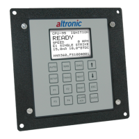
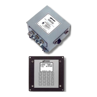
CPU-95 DIGITAL IGNITION SYSTEM
8.0 MOUNTING THE CYCLE TRIGGER
(4-CYCLE ENGINE ONLY)
8.1
The trigger magnet (260604 or 720002) must be mounted on the en-
gine camshaft or other accessory drive operating at camshaft speed.
An M8 (8 mm) tapped hole, 0.5 inches (13 mm) deep is required —
SEE FIGURE 17 or FIGURE 14 for details. For proper operation the mag-
net MUST rotate on a diameter NOT EXCEEDING: 6 inches (150 mm) for
magnet 720002, or 15 inches (375 mm) for magnet 260604.
8.2 Set the engine on the COMPRESSION stroke of no. 1 cylinder with the reset
pin LINED-UP with the reset pickup. The Hall-effect pickup (591014-x)
must be mounted LINED-UP with the trigger magnet (SEE SECTION 8.1)
coincident with the reset pickup and pin being lined-up; SEE FIGURE 4.
The Hall-effect pickup dimensions are shown on FIGURE 15. The air
gap between the Hall-effect pickup and trigger magnet must not
exceed .040" (1.0mm).
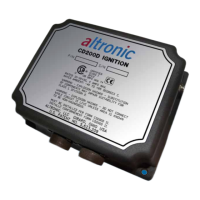
9.0 IGNITION MODULE ELECTRICAL HOOKUP
(REFER TO FIGURE 10)
9.1 GENERAL: The power connections to the CPU-95 must be in accordance
with the National Electrical Code. The CPU-95 is suitable for installa-
tion in Class I, Division 2, Group D locations.
9.2 POWER SOURCE: REFER TO FIGURE 5, power may be supplied as follows:
A. 24-volt battery and charger with 5 amps minimum output (10 amps
when using Ignition Module 791958-16).
B. DC power supply capable of furnishing 24-28 Vdc, 5 amps (10 amps
when using Ignition Module 791958-16).
ALTHOUGH THE DEVICE HAS INTERNAL PROTECTIVE FUSES,
TWO EXTERNAL 10 AMP FUSES NEAR THE POWER SOURCE
ARE RECOMMENDED FOR THE PROTECTION OF ENGINE AND
BUILDING WIRING. THIS WILL REDUCE THE POSSIBILITY OF A
FIRE OCCURRING IN THE EVENT OF A SHORT CIRCUIT IN THE
WIRING. SEE DRAWING 709 961.
WARNING:
NOTE: The Hall-effect signal
and the reset pickup signal
must occur at the same time
for the system to function.
 Loading...