FORM CPU-95 II 4-08
8
CPU-95 DIGITAL IGNITION SYSTEM
11.0
PRIMARY WIRING
11.1
The main wiring harness (293023-x, 293026-x, 793012-x, 793015-x or
793022-x) connects the Ignition Module to the engine junction box.
Refer to FIGURE 1 if it is desired to shorten the conduit length of
the harness. Insert the connector into the Altronic CPU-95 Ignition
Module receptacle and tighten hand-tight; then carefully tighten an
additional one-sixth turn with a wrench.
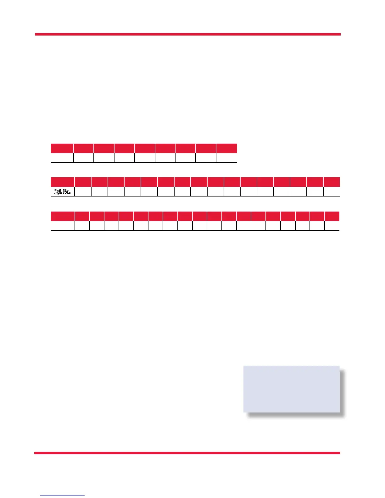
Referring to applicable FIGURE 8 or FIGURE 9, write in the engine r-
ing order below:
IGNITION MODULE 791950-8 (8 OUTPUT) SEE FIGURE 8
Lead A B C D E F K L
Cyl. No.
IGNITION MODULE 791950-16 AND 791958-16 (16 OUTPUT) SEE FIGURE 8
Lead A B C D E F K L M N P R S T U V
Cyl. No.
IGNITION MODULE 791950-18 AND 791952-18 (18 OUTPUT) SEE FIGURE 9
Lead A B C D E F G H K L M N P R S T U V
Cyl. No.
11.2
Connect the harness leads in the junction box in accordance with the
engine’s ring order. The leads from the junction box correspond-
ing to the above system outputs connect to the ignition coil positive
(+) terminals. The “J” lead and the common coil ground lead(s) con-
necting the negative (−) terminals of the ignition coils must be grounded
to the engine in the junction box. Make each ground connection in
the junction box to a separate bolt so that the ground connections
are not stacked on top of each other. On V-engines, run a separate
common ground lead for each bank. SEE FIGURE 6 (unshielded) or
FIGURE 7 (shielded) for coil connection details.
11.3
Primary wire should be no. 16 AWG stranded, tinned copper wire.
The insulation should have a minimum thickness of .016" and be
rated 105°C or higher. Irradiated PVC or polyolen insulations are
recommended. Altronic primary wire number 503188 meets these
specications. All primary wiring should be protected from physi-
cal damage and vibration.
11.4
If two ignition coils per cylinder connected to a common output are
used, use PARALLEL WIRING as shown on FIGURE 6 and FIGURE 7.
11.5
All unused primary wires should be individually taped so that they
are insulated from ground and each other. The unused primary
wires can then be tie-wrapped together for a clean installation.
NOTE: Some secondary
diagnostic features are
limited with two ignition
coils wired in parallel.
 Loading...