www.altronicinc.com
9
INSTALLATION INSTRUCTIONS
12.0
SHUTDOWN WIRING
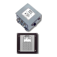
12.1
Two means are provided to shut off the DC-powered CPU-95 Ignition
system.
● a low voltage SHUTDOWN INPUT (terminal 1) in the Ignition Module
● the output “G” lead (shutdown lead) in model 791950-16 only
12.2
To initiate an ignition shutdown using the low voltage shutdown in-
put, ground terminal 1 (SHUTDOWN IN) in the Ignition Module. This in-
put is open for normal operation and is connected to engine ground
for shutdown. Use a switch rated 24 Vdc, 0.5 amps minimum.
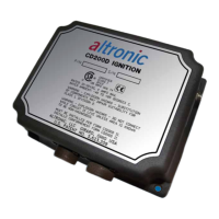
12.3
In the 791950-16 model, a “G” lead is provided to stop the ignition
and to power existing ignition powered instruments. This lead is
open for normal operation and is connected to engine ground for
shutdown. This lead can also be used for oscilloscope analysis.
PLEASE NOTE THE FOLLOWING APPLICATION LIMITATIONS
BETWEEN THE CPU-95 IGNITION SYSTEM AND THESE ALTRONIC
INSTRUMENTS:
WARNING:
DO-3300
DTO-1010
DT/DTH/DTO/DTHO-1200
DT/DTH/DTO-3200
DTUO-4200
The above Altronic ignition-powered tachometers and overspeed
devices will NOT function correctly with any CPU-95 system operat-
ing in the Double-Strike mode.
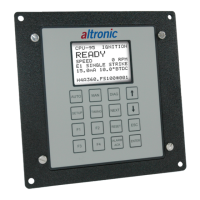
NOTE: Tachometer and
overspeed functions are pro-
vided by the CPU-95 Display
Module; see sections 4.0
and 9.4 of operating instruc-
tions form CPU-95 OI. If a
separate device is needed,
Atlronic models DSG-
1201DU/DUP or DTO-1201P
will function with all CPU-95
systems.
 Loading...